Last updated on October 19, 2024
In this project I plan to design and build a kitchen timer. We don’t have one in our kitchen and it feels like the perfect project for a hot August weekend. I’m writing this blog post while I’m building the device, hopefully this will make it more interesting as I’m sure I’ll come up against some problems and this will document solutions that I find.
The basic requirement is a device that allows a countdown timer to be set, for a certain number of minutes and seconds, after which the device audibly and visually alerts that the countdown is complete.
Stage 1 – Brainstorming ideas
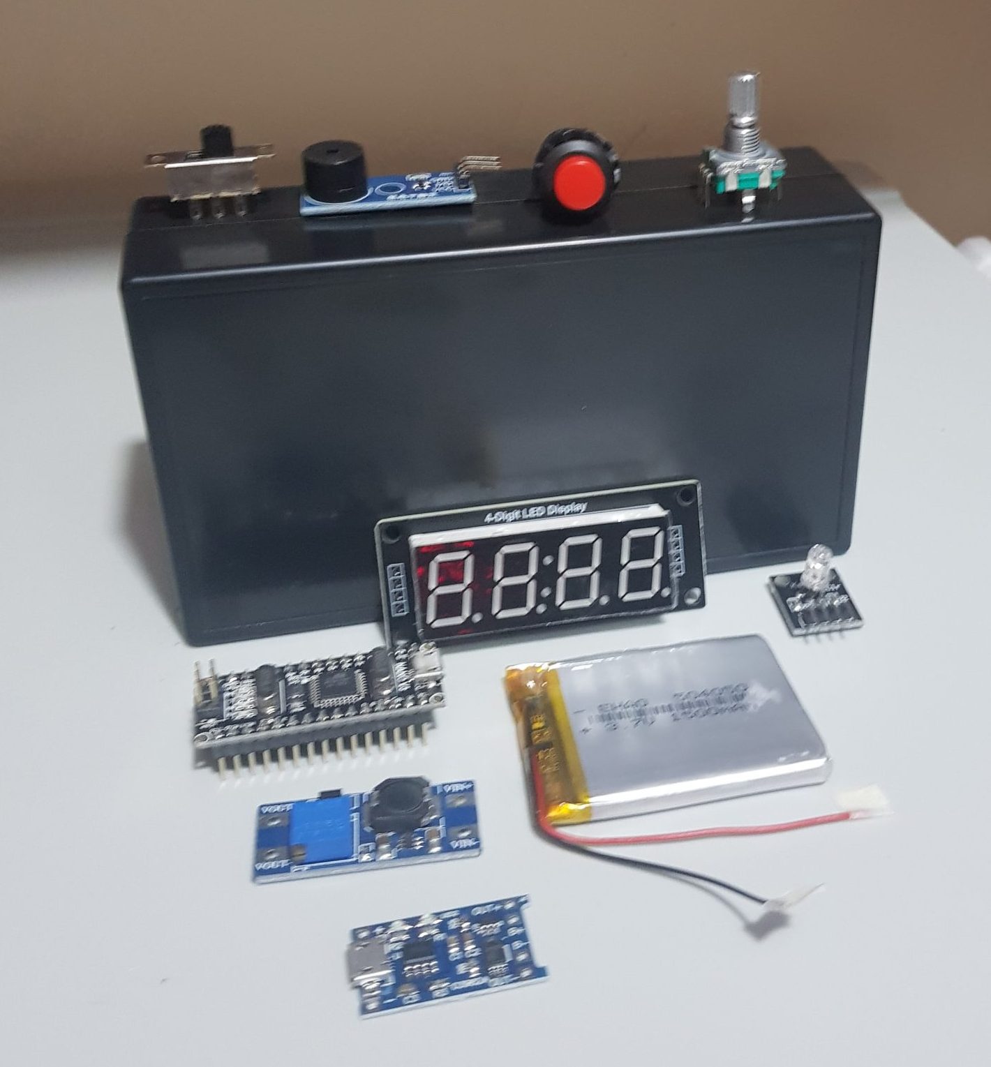
Firstly – let’s brainstorm the key components that we know will be used in our device.
Clock – a display showing visually how many minutes/seconds are left in the countdown
On/Off switch – a switch that turns power to the device on and off
Several buttons to set mode / start and stop timer
Speaker – for an audible alarm at the end of the countdown
Lights – for a visual alarm at the end of the countdown and to show the mode status
Battery pack – to power the device as it needs to be portable
Project box – the device needs to be contained inside a small box which can survive in a kitchen setting
This will be my first portable device. I have some Lithium ion polymer batteries and charging modules, so I can use them along with a step-up convertor to get a steady 5 volts for my microcontroller. All my previous devices needed to be connected to a USB socket, so this will be an exciting step forward for me.
Stage 2 – Determining user actions
Next – let’s list the actions that the user will want to execute when interfacing with our device. Once we know these we can determine what physical controls our device needs.
Power on – give power to the device, start it up
Power off – cut power to the device, turn it off
Start timer – begin our countdown timer
Pause timer – pause our countdown timer
Reset timer – set the timer to 0
Increase countdown mins – adjust the countdown timer on the device
Increase countdown seconds – adjust the countdown timer on the device
Decrease countdown mins – adjust the countdown timer on the device
Decrease countdown seconds – adjust the countdown timer on the device
Stage 3 – Mapping controls to actions
Now – let’s decide how our physical controls can initiate those actions.
Power on – turn power switch to the right
Power off – turn power switch to the left
Start timer – press a button
Pause timer – press a button
Reset timer – hold down a button
Increase countdown mins – rotary encoder turn right
Increase countdown seconds – rotary encoder turn right
Decrease countdown mins – rotary encoder turn left
Decrease countdown seconds – rotary encoder turn left
When creating an MVP (minimum viable product) we should try to limit the number of physical items as much as we possibly can. Every additional button will make our device more complex to build, and increase the risk of problems occuring.
I will be using an Arduino Nano compatible device. I’m sure many kitchen timers out there don’t use microcontrollers as powerful as the ATmega328 on an Arduino Nano board, for sure it’s overkill, but from a hobbyist’s point of view it’s much cheaper and sensible to use a $3 Nano than attempt to use several more specific ICs and transistors along with a custom PCB.
Basically, yes if you were to design a device for mass production you would not base it on an Arduino Nano. For a hobby project with limited production numbers this is the way to go.
Stage 4 – Planning the code
Now let’s write some pseudo-code to figure out what we need to do on the ATmega328 processor.
Setup function:
- Reset state to set timer – when you turn the device on, it should be ready to set-up
- Reset state for ‘what we are editing’ – we will start by editing minutes
- Set pins to input/output where required – ready to send or receive messages
Initialise any additional libraries we will use – we will use 3rd party libraries to speed up development
Looping function
If the rotary encoder button is pressed – change what we are editing – from the minutes to the seconds and back
- If the rotary encoder is rotated – change the number we have for minutes/seconds – up or down depending on the direction the encoder was turned
- If the button is pressed change our state from setting the countdown timer start time to running the countdown, if we are in countdown mode, pause the countdown
- If the reset button is pressed, return us to the set timer mode with the countdown we started from
- If we are in the countdown mode – reduce the time if a second has passed.
- If we are in the countdown mode – If the time runs out, then make an audible sound and set state to end
- If we are in the end state keep making a noise until the device is reset
The question here is, how many buttons do we need. We could make do with one button, with the device resetting if the user holds the button down for several seconds. As I want to limit the amount of physical items for this MVP version, I will stick to one button.
Stage 5 – Building a prototype
The next step is to create a prototype, on which we can write the software and confirm that we are capable of developing such a device, before constructing too much in the way of hardware. We can see how the device functions and if we need to make further hardware adjustments.

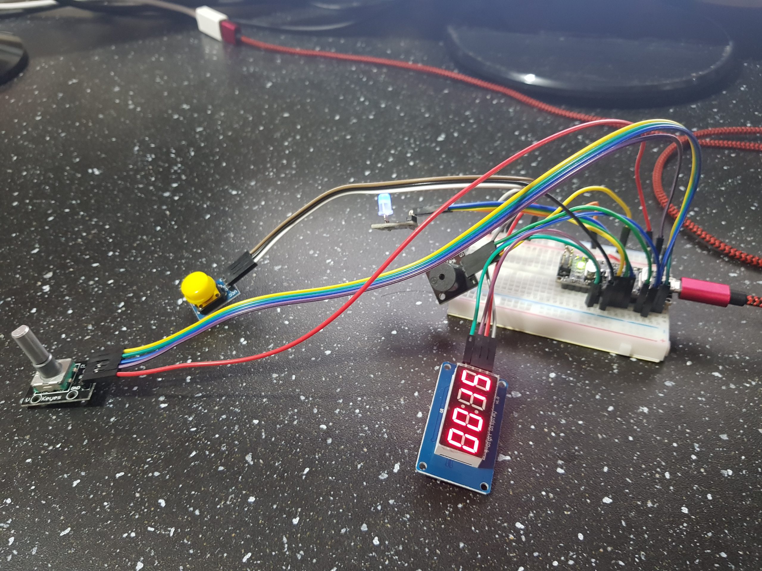
As you can see I have constructed a prototype on a breadboard. I’m using a smaller display and a different type of button. Before doing any actual construction of the device it is critical to know that it will work. It’s much easier to add/remove buttons/components now than do it with the device half built!
I built the prototype one component at a time, and I highly recommend this course of action. Firstly I connected up my 4-digit display and ensured that I could set whatever value I wanted. I used this third party library that I found on the Internet – https://github.com/AKJ7/TM1637 – now there is part of me that wanted to get the datasheet for the display and build my own code to set digit values, but then I reminded myself that this weekend is about building a kitchen timer not about writing a TM1637 library.
Using a library to simplify using a component is a great time saver, although it does feel somewhat like cheating to me. Though in reality I guess I just have to accept that as the famous saying goes, “I can see further because I’m standing on the shoulders of giants”. Libraries such as this one allow us to plug in our display and be up and running a couple of minutes later with just a couple of lines of code. This makes the coding part of the project a bit easier than it would be without using a library containing functions to easily manipulate the display module.
You might have noticed that I am now talking in the past tense. Building the prototype was enough work without updating this post in real time. The prototype is now working very nicely.
After connecting the display I connected a speaker module that I got in a collection of ‘Arduino sensors’. The default ‘tone()’ function in the Arduino libraries is fairly quiet and so I went on an Internet search to find a way to make more noise. I discovered the toneAC library – https://github.com/teckel12/arduino-toneac – this library has you connecting the speaker to two IO pins on the Arduino rather than one IO pin and ground. The great thing about this library is that it allows you to make much louder sounds with the same speakers.
With both the ToneAC library and the TM1637 library I uploaded a sample script to my Nano to test the functionality, this was much faster than adding library code to my countdown timer program then testing to see if the library was to my liking.
The button and LED components are very straightforward to use and I was able to take code from my earlier projects. Buttons are simple once you’ve figured out a decent way to ‘debounce’ them. This is a phenomena where by a button is pressed but due to the way the button completes the circuit at the moment on impact there is typically a bit of fluttering of pressed/not pressed for a few milliseconds. If you don’t deal with this properly then your program will take readings that suggest that the button has been pressed about 10 times for every time it is actually pressed.
All that my ‘de-bouncing’ code does is remembers when we last changed the button state and wait 50 milliseconds until treating any other state change as a legit change.
Getting to this point has taken a whole afternoon. Tomorrow I will return and build the device itself inside the project box.
Here is a video of the current state of the device – as you can see there are some issues – for one I am ending the timer when the second goes down to 0 when I should wait one more second. Also currently it’s a fixed 15 second countdown timer, which isn’t very useful beyond heating up tortillas. That’s because I haven’t added the code to read the rotary encoder values yet.
Day 2 – Building the kitchen timer device
I have just completed the code for reading the rotary encoder. It’s very straightforward and I would recommend following a tutorial online if you don’t know how they work. They let us determine which direction the knob is being rotated. We take one direction to represent an increase, and the other direction to be a decrease.
With that done the source code is now pretty much complete – here is what I came up with. (I have uploaded this to Github as well)
// COUNTDOWN TIMER
// Written by Oli Norwell - August 2020
// www.olinorwell.com
// Tutorial: https://www.olinorwell.com/designing-and-building-a-digital-kitchen-timer
// MIT licence - do whatever you want with it - it would be nice to hear if you have improved it
//
// We split the code into modules
//
// Countdown - everything to do with an actual countdown
// Rotary Encoder - everything to do with the rot enc that sets our start time
// Sound - everything to do with the sound we output
// Display - everything to do with the 7 seg 4 digit display

//#define DEBUG		// if this is active then we output messages through serial

// Countdown state
#define COUNTDOWN_SETUP     0
#define COUNTDOWN_ACTIVE    1
#define COUNTDOWN_PAUSED    2
#define COUNTDOWN_END       3

int countdownState = COUNTDOWN_SETUP;		// begin with us ready to set a countdown time
int countdownMins = 0;				// current mins to go
int countdownSecs = 15;				// current secs to go
int countdownStartMins = 0;			// what did we start with? used when resetting
int countdownStartSecs = 15;

long lastCountdownChange = 0;			// how long since we adjusted the countdown

// Timer button
#define BUT_PIN           4			// where is our button connected (other end to ground)
long butLastChange = 0;				// when did we last register a state change?
int butLastState = LOW;				// what was the last state of the button?

// Rotary Encoder (https://en.wikipedia.org/wiki/Rotary_encoder)
#define ROT_UPDATE_MINS   0			// Mode to edit mins
#define ROT_UPDATE_SECS   1			// Mode to edit seconds

#define ROT_PIN_A       12			// Pin that pin A of rot enc is connected to
#define ROT_PIN_B       13			// Pin that pin B of rot enc is connected to
#define ROT_PIN_BUT     11			// Pin that button pin of rot enc is connect to (other to ground)

int rotPinAState = 0;				// State of pin A of rot enc
int rotPinBState = 0;				// State of pin B of rot enc
int rotPinALastState = 0;			// Previous state of pin A (we don't care for B)
int rotWhichUpdate = ROT_UPDATE_MINS;		// what is it currently updated? mins or secs?
int rotButState = 0;				// State of the rot enc button
long rotButLastChange = 0;			// when was the button state last changed?
int rotButLastState = HIGH;			// previous state of rot enc button

// Display (I am using a fairly large 4 digit 7 segment display with the TM1637 IC)
#include <TM1637.h>				// https://github.com/AKJ7/TM1637
TM1637 tm1637(2, 3);				// Initialise library pin 2 to clock, pin 3 to DIO

// RGB LED light - an LED with 4 pins, RGB and ground
#define LED_MODE_NOTHING        0		// what state our LED is in, which determines its colour
#define LED_MODE_SETUP          1
#define LED_MODE_COUNTDOWN      2
#define LED_MODE_PAUSED         3
#define LED_MODE_END            4

int ledMode = LED_MODE_NOTHING;			// store our current state
long ledModeLastChange = 0;			// used for blinking lights (not done yet)
int ledModeBlinking = 0;			// used for blinking lights (not done yet)
int ledPinR = 5;				// pin on Arduino connected to LED R pin
int ledPinB = 6;				// pin on Arduino connected to LED B pin
int ledPinG = 7;				// pin on Arduino connected to LED G pin

void updateLED();				// Function to update the state of the light
void setLEDMode(int mode);			// Function to set the state of the light

// Sound
#include <toneAC.h>         // ToneAC library - which allows us to get a louder tone than the Arduino library
				// https://github.com/teckel12/arduino-toneac

#define SOUND_MODE_SILENCE      0
#define SOUND_MODE_ALARM        1

#define SOUND_STATE_SILENCE     0
#define SOUND_STATE_TONE1       1
#define SOUND_STATE_SILENCE2    2
#define SOUND_STATE_TONE2       3

int soundMode = SOUND_MODE_SILENCE;      // By default we sit in silence
int soundState = SOUND_STATE_SILENCE;	 // By default silence
int soundFreq = 2100;			 // our starting frequency
int soundDir = 1;			 // If frequency is getting higher or lower
long soundLastUpdate = 0;		 // when did we last update the sound frequency

// Function to setup the LED output pins
void setupLED()
{
  pinMode(ledPinR, OUTPUT);
  pinMode(ledPinB, OUTPUT);
  pinMode(ledPinG, OUTPUT);

  return;
}

// function to set the LED mode
void setLEDMode(int mode)
{
  ledMode = mode;

  return;
}

// Update the LED - depending on the mode decide what our LED pins should output to the component
void updateLED()
{

  // depending on the LED mode we create a different colour on our RGB LED component

  if(ledMode == LED_MODE_NOTHING)
  {
    digitalWrite(ledPinR, LOW);
    digitalWrite(ledPinB, LOW);
    digitalWrite(ledPinG, LOW);
  }
  else if(ledMode == LED_MODE_SETUP)
  {
    digitalWrite(ledPinR, HIGH);
    digitalWrite(ledPinB, LOW);
    digitalWrite(ledPinG, LOW);
  }
  else if(ledMode == LED_MODE_COUNTDOWN)
  {
    digitalWrite(ledPinR, LOW);
    digitalWrite(ledPinB, HIGH);
    digitalWrite(ledPinG, LOW);
  }
  else if(ledMode == LED_MODE_PAUSED)
  {
    digitalWrite(ledPinR, HIGH);
    digitalWrite(ledPinB, HIGH);
    digitalWrite(ledPinG, LOW);
  }
  else if(ledMode == LED_MODE_END)
  {
    digitalWrite(ledPinR, LOW);
    digitalWrite(ledPinB, LOW);
    digitalWrite(ledPinG, HIGH);
  }

  return;
}

// Function to setup our button
void setupBut()
{
  digitalWrite(BUT_PIN, HIGH);
  pinMode(BUT_PIN, INPUT_PULLUP); // Input with a pull-up resistor (so high when not connected to ground physically by the button)

  return;
}

// Function to deal with our main button being pressed
void butPressed()
{
  // This adjusts the state of our device, which uses a finite state machine with 4 different possible states

  if(countdownState == COUNTDOWN_SETUP)
  {
    // If we are in the setup mode, then set our mode to active so the countdown can begin
    countdownStartMins = countdownMins;
    countdownStartSecs = countdownSecs;

    countdownState = COUNTDOWN_ACTIVE;
    setLEDMode(LED_MODE_COUNTDOWN);	// change what the LED state is
  }
  else if(countdownState == COUNTDOWN_ACTIVE)
  {
  // If we are currently in the active countdown mode - move us to the paused state
    countdownState = COUNTDOWN_PAUSED;
    setLEDMode(LED_MODE_PAUSED);	// change what the LED state is
  }
  else if(countdownState == COUNTDOWN_PAUSED)
  {
  // If we are currently in the paused countdown mode - move us back to the active state
    countdownState = COUNTDOWN_ACTIVE;
    setLEDMode(LED_MODE_COUNTDOWN);	// change what the LED state is
  }
  else if(countdownState == COUNTDOWN_END)
  {
  // If our countdown is already over, then move us back to the setup stage
    setLEDMode(LED_MODE_SETUP);

    killSound();			// stop our alarm sound

    countdownState = COUNTDOWN_SETUP;	// reset values ready for the setup state again
    countdownMins = countdownStartMins;
    countdownSecs = countdownStartSecs;
  }

  return;
}

// Function to update our main button state
void updateBut()
{
  // This is my simple debouncing code, that will ensure 50ms have passed before
  // allowing further state changes
  if(millis() - butLastChange > 50)
  {
    if(digitalRead(BUT_PIN) == LOW)
    {
      if(butLastState == HIGH)
      {
        butLastChange = millis();
        butLastState = LOW;

        butPressed();		// run the function for a button press
      }
    }
    else
    {
      butLastState = HIGH;
    }
  }

  return;
}

// Function to setup the rotary encoder
void setupRotEnc()
{
  pinMode(ROT_PIN_A, INPUT_PULLUP);		// Input with an internal pull-up resistor
  pinMode(ROT_PIN_B, INPUT_PULLUP);		// Input with an internal pull-up resistor
  pinMode(ROT_PIN_BUT, INPUT_PULLUP); 		// Button with an internal pull-up resistor
  // this means that when not doing anything the value will be pulled to high

  rotPinALastState = digitalRead(ROT_PIN_A);	// see what the current value is and set to first old value

 return;
}

// Function to deal with the rot enc button being pressed
// the user can push in the rotary encoder dial to press the button
void rotButPressed()
{
// all we do is change what was being edited, from mins to secs and back
  if(rotWhichUpdate == ROT_UPDATE_MINS)
  {
      rotWhichUpdate = ROT_UPDATE_SECS;
  }
  else
  {
      rotWhichUpdate = ROT_UPDATE_MINS;
  }

// Note: I plan to add a 'reset' option if the button has been held down
// for say over 3 seconds, this isn't yet implemented

  return;
}

// Function to deal with the rot enc decreasing our value
void rotUpdateSettingDown()
{
// Depending on what we are currently updating, make the change
// but only if mins or secs are larger than 0
  if(rotWhichUpdate == ROT_UPDATE_MINS)
  {
    if(countdownMins > 0) countdownMins--;
  }
  if(rotWhichUpdate == ROT_UPDATE_SECS)
  {
    if(countdownSecs > 0) countdownSecs--;
  }

  return;
}

// Function to deal with the rot enc increasing our value
void rotUpdateSettingUp()
{
// Depending on what we are currently updating, make the change
// but only if the mins are less than 99 or seconds less than 59
  if(rotWhichUpdate == ROT_UPDATE_MINS)
  {
    if(countdownMins < 99) countdownMins++;
  }
  if(rotWhichUpdate == ROT_UPDATE_SECS)
  {
    if(countdownSecs < 59) countdownSecs++;
  }

  return;
}

// Update our rotary encoder
void updateRotEnc()
{
   rotPinAState = digitalRead(ROT_PIN_A);		// Grab the state of pin A
   rotPinBState = digitalRead(ROT_PIN_B);		// Grab the state of pin B

   // If pin A has changed state - then depending on whether it is now the same as B or not we can see what way it was turned
   if(rotPinAState != rotPinALastState)
   {
       if(rotPinBState != rotPinAState)
       {
          rotUpdateSettingDown();
       }
       else
       {
         rotUpdateSettingUp();
       }
   }

   // Record the state as the new 'old state'
   rotPinALastState = rotPinAState;

  // Rot button - with simple de-bouncing code - ensuring we wait 50ms before accepting a change of state
  if(millis() - rotButLastChange > 50)
  {
    if(digitalRead(ROT_PIN_BUT) == LOW)
    {
      if(rotButLastState == HIGH)
      {
        rotButLastChange = millis();
        rotButLastState = LOW;
        rotButPressed();
      }
    }
    else
    {
      rotButLastState = HIGH;
    }
  }

   return;
}

// Setup our display using the 3rd party library we have chosen to use
void setupDisplay()
{
    tm1637.init();			// Init the display
    tm1637.setBrightness(5);		// Set a medium brightness

    return;
}

// Update our display - the 4 digit value we want to put on the display is the mins * 100 + secs
void updateDisplay()
{

  int val = countdownMins * 100;
  val += countdownSecs;

	// e.g. 3 mins 40 secs.... 3 * 100 = 300 + 40 = 0340 for the display.
	// 15 mins 8 secs = 15 * 100 = 1500 + 8 = 1508 for the display

    tm1637.display(val);	// Using the library we are using we can simply send it a value to display

    // note: I haven't set the : in the centre of the display - this was an oversight but could be easily added

    return;
}

// Stop making sound
void killSound()
{
  toneAC();				// Set sound to nothing
  soundMode = SOUND_MODE_SILENCE;   	// Set our sound mode to silence

  return;
}

// Update our sound module
void updateSound()
{
  if(soundMode == SOUND_MODE_SILENCE)
  {
      // The sound of silence....
  }
  else if(soundMode == SOUND_MODE_ALARM) // We are in alarm mode, tweak our noise
  {
  	// Note how this is a finite state machine and isn't blocking. We change the tone every so often
  	// but the rest of our program continues while we are making noise - useful if we added features such
  	// as a network connection which we'd need to give time to.

    if(millis() - soundLastUpdate > 100)	// Every 100ms we adjust the tone
    {
      soundLastUpdate = millis();		// Mark when we are making this change

        // Change state depending on current sound state
        if(soundState == SOUND_STATE_SILENCE) // We were silent - so this is us starting to make noise
        {
            if(soundDir == 1) soundFreq += 20;
            else soundFreq -= 20;
            if(soundDir == true && soundFreq > 2300) { soundDir = false; }
            if(soundDir == false && soundFreq < 1900) { soundDir = true; }

            // move to playing tone1
            toneAC(soundFreq);
            soundState = SOUND_STATE_TONE1;
        }
        else if(soundState == SOUND_STATE_TONE1) // We were making tone1, now be silent a bit
        {
            toneAC();
            soundState = SOUND_STATE_SILENCE2;	// Go to the second silent mode
        }
        else if(soundState == SOUND_STATE_SILENCE2) // We were having a silent moment, make noise again
        {
            // move to playing tone1
            toneAC(2100);
            soundState = SOUND_STATE_TONE2;
        }
        else if(soundState == SOUND_STATE_TONE2) // Return to the silence mode
        {
            toneAC();
            soundState = SOUND_STATE_SILENCE;
        }
    }


  }

  return;
}

// Update our countdown
void updateCountdown()
{

  // If a second has passed then we update the countdown
  if(millis() - lastCountdownChange >= 1000)
  {
    lastCountdownChange = millis();		// Record when we made this change

    countdownSecs--;				// Reduce seconds by 1

    if(countdownSecs < 0) 			// If seconds are now -1, then we have to reduce mins
    {
      countdownSecs = 59;			// Set seconds to 59, which is what -1 really means to us
      countdownMins--;				// Reduce minutes by 1

      if(countdownMins < 0) 			// If minutes is now -1, then we are done
      {
        countdownState = COUNTDOWN_END;		// Set countdown state to the countdown having ended
        soundMode = SOUND_MODE_ALARM;		// Set the sound state to make a lot of noise
        countdownSecs = 0;			// Set our countdown to 0 mins, 0 secs (as mins was -1)
        countdownMins = 0;
      }
    }
  }

  return;
}

// Our setup function - ran once on power up
void setup()
{

// Enable serial debugging if we desire it
#ifdef DEBUG
  Serial.begin(9600);
#endif

  // Setup our various modules
  setupBut();
  setupRotEnc();
  setupDisplay();
  setLEDMode(LED_MODE_SETUP);

  return;
}

// Our loop function - will run forever unless we cut the power or run out of it
void loop()
{
  // Update the countdown, but only if we are actively counting down
  if(countdownState == COUNTDOWN_ACTIVE) updateCountdown();

  // Update our various modules
  updateRotEnc();
  updateDisplay();
  updateSound();
  updateBut();
  updateLED();

return;
}

// Go luck if you decide to build this device! Let me know how you get on
Building the device itself represents some different challenges from building the breadboard prototype. Primarily the need to convert a plastic box into a shell for an electrical device.
Stage 6 – The battery backpack
To power our kitchen timer we’re going to use a rechargable battery. This will free our device from needing to be plugged in. As a kitchen timer this will mean it can be moved around at will and placed where it will be most useful.
The batteries that I have though provide 3.7 volts, whereas the Arduino Nano needs a stable 5 volt input if powered directly. Not only is 3.7 volts not enough, as the battery loses charge that voltage will change. So we need to use a ‘step-up’ convertor, which takes a variable low voltage and boosts it up to the desired amount.
I happened to have a module that takes a voltage of between about 1 and 4 volts and boosts it up to anything between 2 and 20 volts. I used a small screwdriver to adjust the output voltage to the 5 volts that we will need for this project.
The countdown timer will need an on-off switch. As this will be connected to the feed from the battery, I’ve realised that it makes sense to have all the battery components located on the bottom part of the project box that I have. It splits in half nicely and then clicks back together.
The on-off switch will need to poke through a hole in the top of the box. This hole is rectangular in size.

As you can see my method for creating hole in the project box is to stick some masking tape down first, then draw the shape of the hole that is needed. I then drill holes at the edges of the rectangle and use a box-cutter to remove what remains of the plastic. This isn’t an exact science and I want to improve my technique, as the resulting hole wasn’t exactly perfect.
The battery is connected to a charging module which has a micro USB socket. This also needs to peep out of the project box. I did the same as with the on-off switch and cut out a rectangle on the left hand side of the box.
I then used a hot-glue gun to apply a generous amount of hot glue to both items. If you haven’t got a hot-glue gun I highly recommend getting one, they are fantastic for quickly connecting components that don’t have useful holes for screws and stand-offs. It’s not the perfect solution but in my experience the components are held strongly enough for hobby projects such as this one.
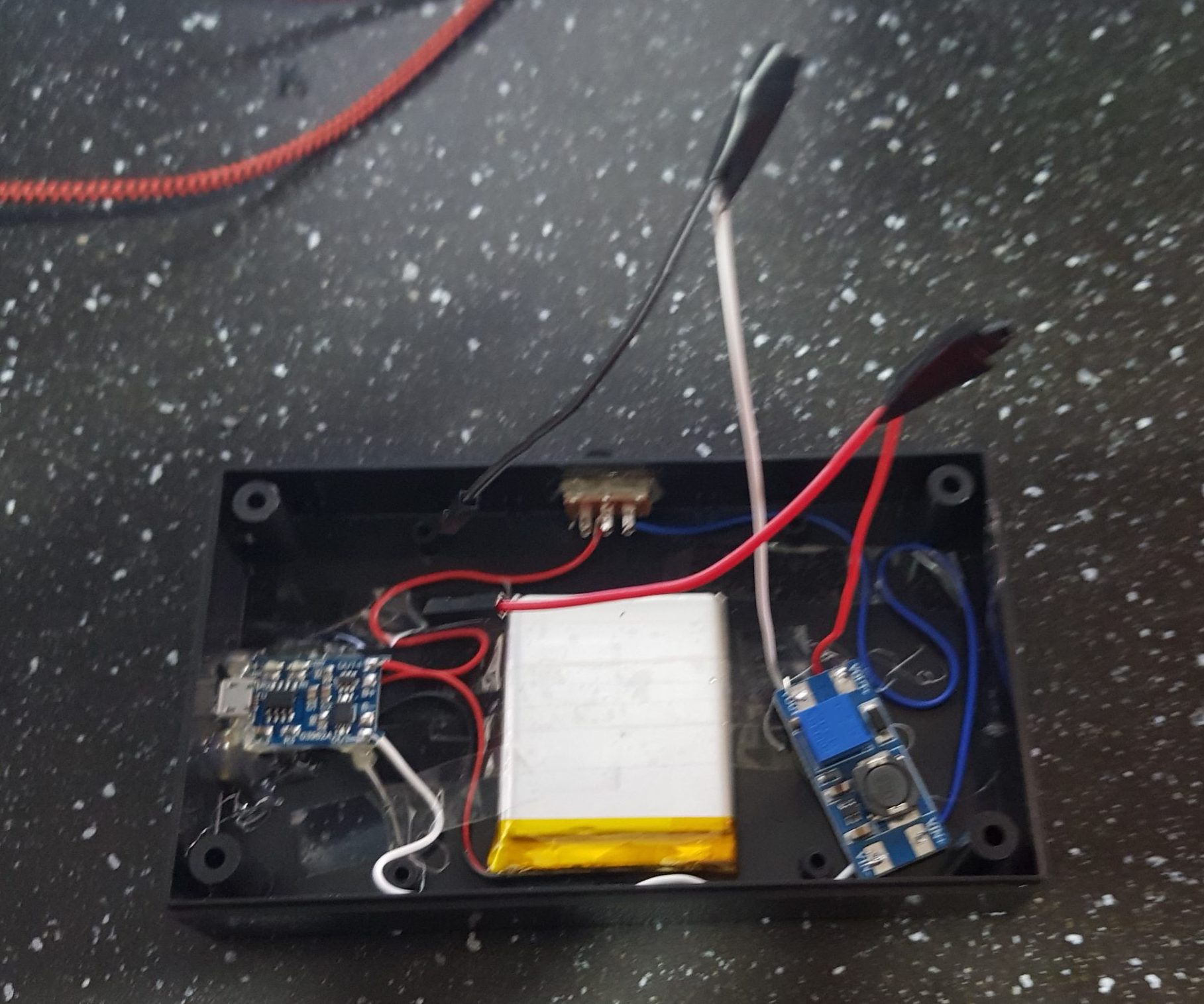
Below is the completed ‘battery pack’ bottom compartment of the kitchen timer. The battery is held down with tape in case I need to remove it and replace it. The component on the right is the step-up/boost convertor which takes what we get from the battery and increases the voltage to 5v. The raised red and white cables are ready to be attached to the rest of the project.
Stage 7 – building the front section
With half the project complete and nicely outputting a stable 5v we can move onto building the front section. This of course will house the countdown timer, our button, our rotary encoder and the RGB LED light.
As with the back of the timer I used masking tape to measure the hole for my 4-digit display. It was a pain to cut out, I drilled many holes then attempted to gouge out the rest of the plastic. I need to come up with a better technique for this. In the end I managed to get it the right size for the display to pop through. The holes for the speaker and LED were much easier. On the top of the device I then drilled two more holes, one on the left for my main control button, and then one on the right for my rotary encoder.
As you can see in the photo. I then connected the components to my Arduino Nano (top, connected to the USB cable). Before long the number of wires was beginning to get out of hand. This is why I cannot stress enough, limit the amount of components in your project, if you don’t this is the moment when you suddenly find yourself in a jungle of cables and things starting to fall apart.
As it was I managed to get everything connected and the device working. As you can see I used a small bit of protoboard with a set of female dupont connectors soldered to it (top, to the right of the Nano) to collect my ground pins, as the Arduino doesn’t have enough ground pins for all the components. For anything but the simplest of projects you will probably need to do something similar. For me this solution works better than trying to solder multiple wires together.
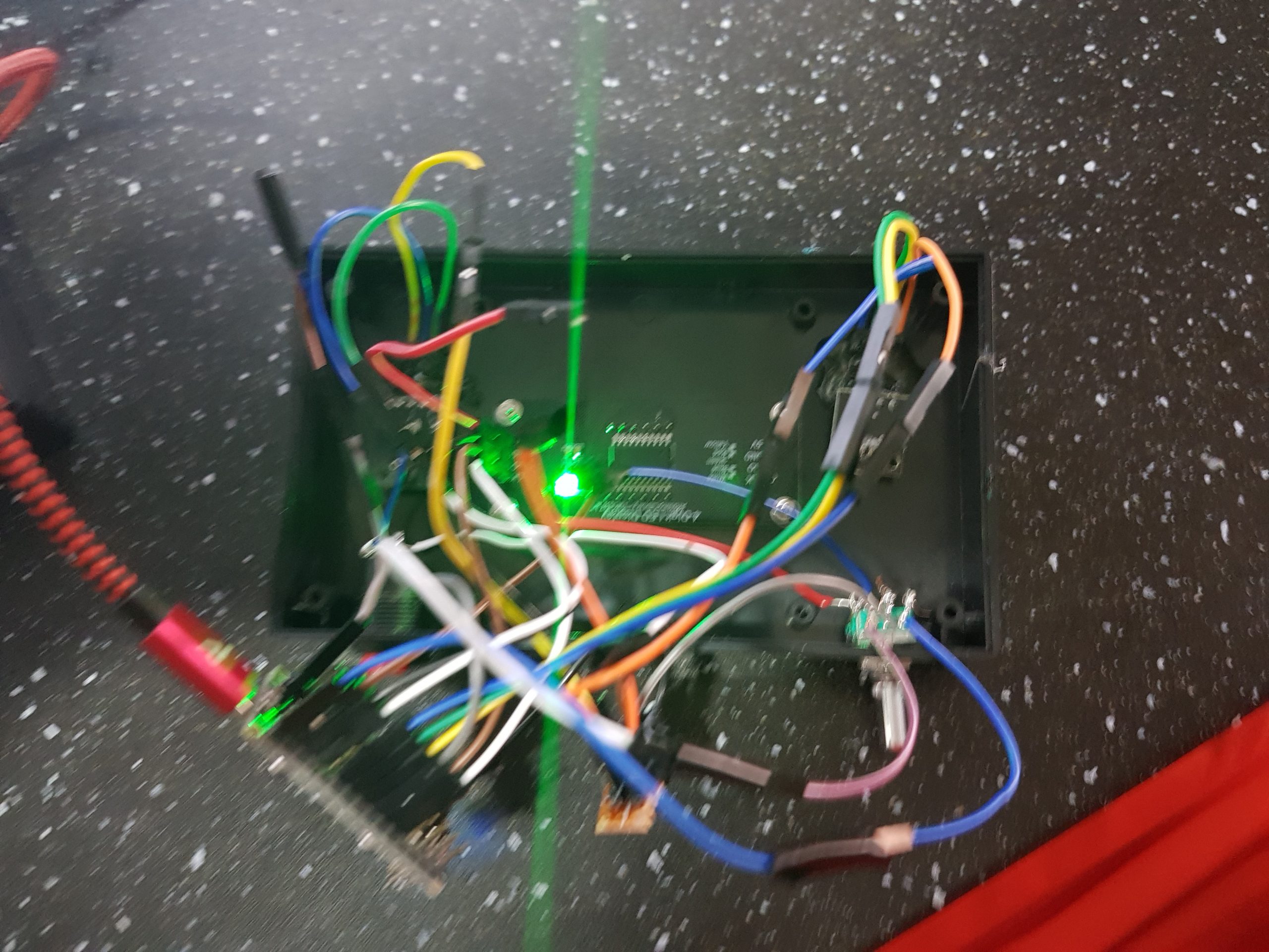
As you can see above, the mess of wires was beginning to get out of hand.
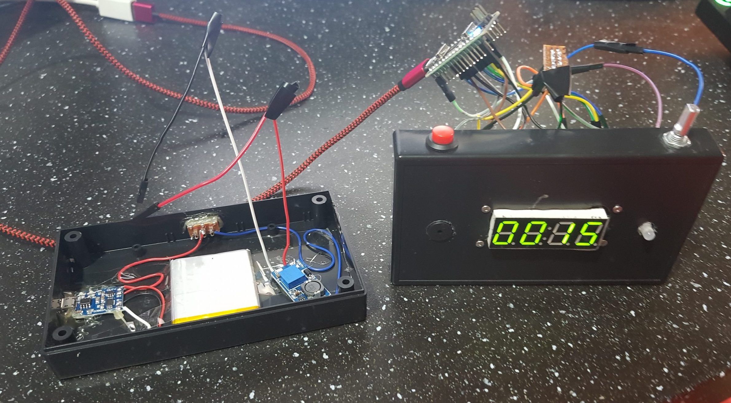
All that was left to do was to connect the battery backpack to the front of the device, then get the box to close. I attached the positive wire from the battery to the 5V input on the Arduino Nano, then the ground wire from the battery to one of the ground pins. The two sides clicked nicely together, leaving me with the finished article. A quick test showed that all was working correctly. Yes it looks slightly ghetto, but it works! and is as sturdy as a tank.

Here’s a video of the final device in use demonstrated by my wife. A week after construction I’ve heard the alarm go off at least 7 or 8 times, so it’s clearly getting used a fair bit!
Ideas for improvements
Unfortunately I realised a few hours after completing the project that the LED wasn’t being lit. I think perhaps when I glued it down to the shell a wire came loose. I could take it apart and reconnect the LED but honestly it isn’t needed for the device to be useful, so I have decided to leave it be.
I think to improve the device I would have the countdown timer mounted further back – so that the ugly white top of the display didn’t stick out. I plan to paint that, but for now it’s a bit of an eye sore.
Modifying the device to keep tabs on multiple timers would be pretty easy – so that’s an idea for version 2. Additionally I am considering using one of the ESP8266 boards which have built in wi-fi – I could then run a web server and allow users to check on the timers remotely, and also pause/set the timers remotely. This would of course potentially use a lot more power, so that’s something to consider there.
As for simple improvements – I like the idea of a 5 minute warning sound – that advises you that you have 5 minutes left on the countdown. Also I had the idea of adding a vibration module, in case the device needed to give a tactile alarm rather than an audible one. Though of course in its current size and form it’s not like you would have it in your pocket, so being able to vibrate is of little use.
Summary
I’m very pleased with this project. It was completed from start to finish in around 10 hours over a weekend. Since it was completed the timer has been used several times, it’s always great when you build something and it’s actually used in real life!
I hope you found this post interesting, please let me know if you decide to build one yourself, I’d be very interested to see photos of timers people have built.
The the source code for this project can be found on Github.
Hi,
I was searching for exactly this! Thank you!
But I have a grave problem: The rotary encoder isn´t working. I tried two different ones. And the display is just giving jibberish “15u5” When I turn the encoder it shortl (some ms) changes to “19u5” but quickly reverts to “15u5”. I checked the cables, encoder and pins if they are right and they are. What yould it be?
Thanks in advance 🙂
“Dominik Kovacs wrote:
But I have a grave problem: The rotary encoder isn´t working. I tried two different ones. And the display is just giving jibberish “15u5” When I turn the encoder it shortl (some ms) changes to “19u5” but quickly reverts to “15u5”. I checked the cables, encoder and pins if they are right and they are. What yould it be?”
I have same problem .