Last updated on October 19, 2024
Arduino Live Wifi Web Scoreboard
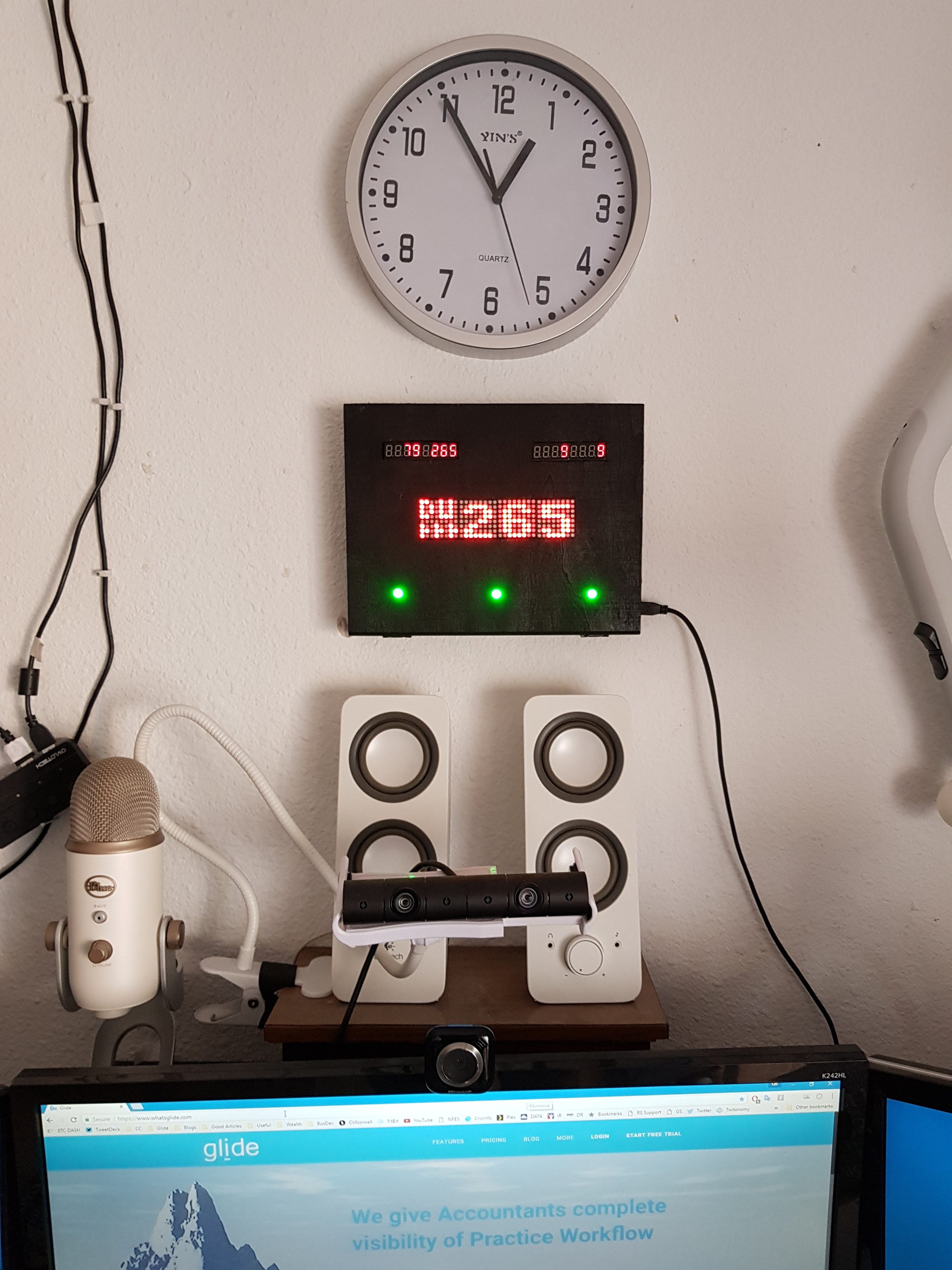
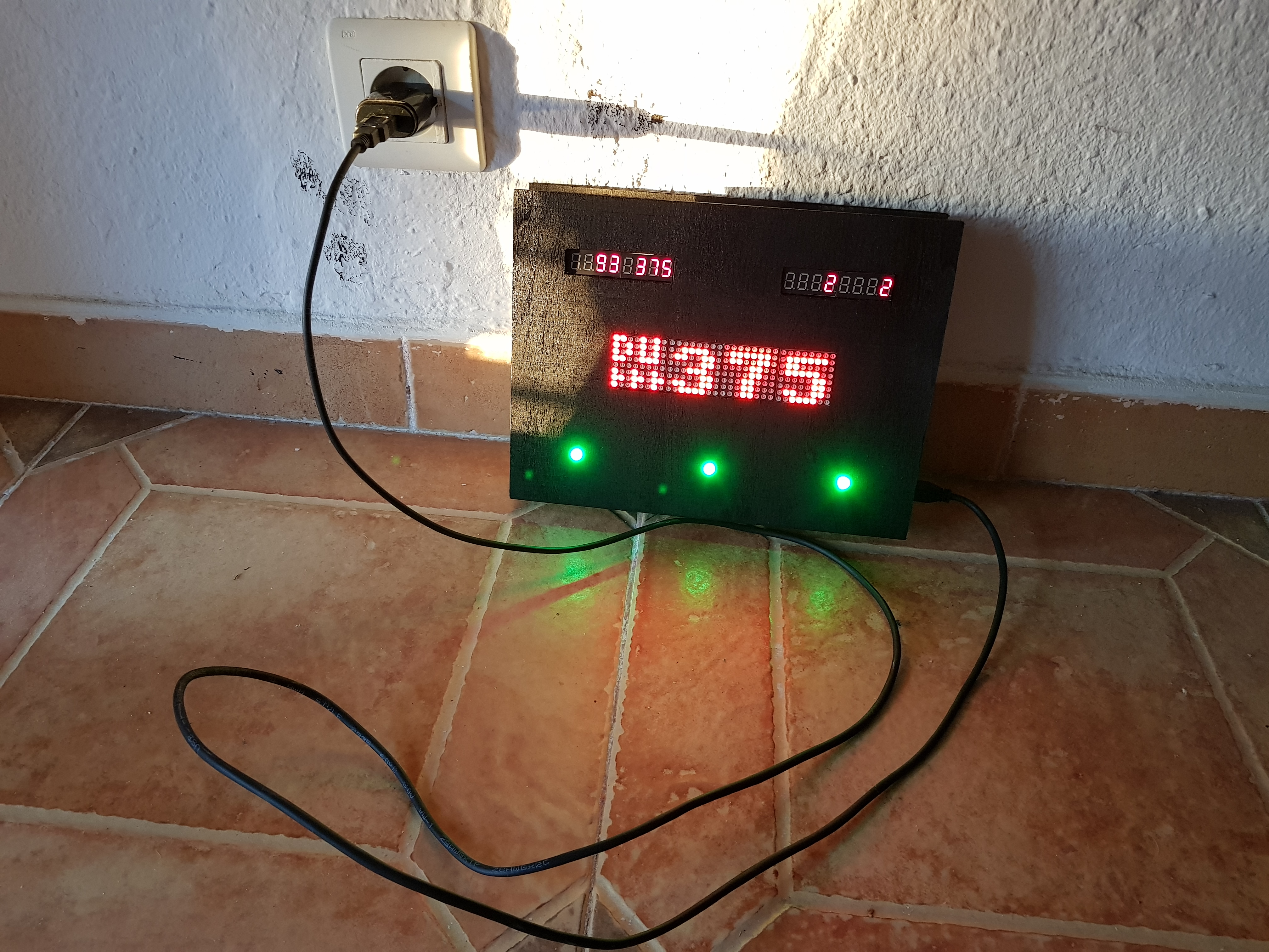
In this tutorial I am going to explain how I created a digital scoreboard with LEDs, a large dot-matrix display and numerical 8-digit totals. The device uses a WiFi chip to connect to the Internet to get status values such as totals and live counts, plus statuses such as on/off for the LEDs. The device is powered by a generic USB power adaptor. Under the hood it uses an Arduino Mega compatible board, which are readily available, economical, and communicate well with the ESP8266 chips.
The scoreboard is made from a wooden box, with hinges and a clip to allow for access to the internals when needed. Power usage is minimal, running the device 24/7 for a year with WiFi connections every minute will cost less than 1 euro.
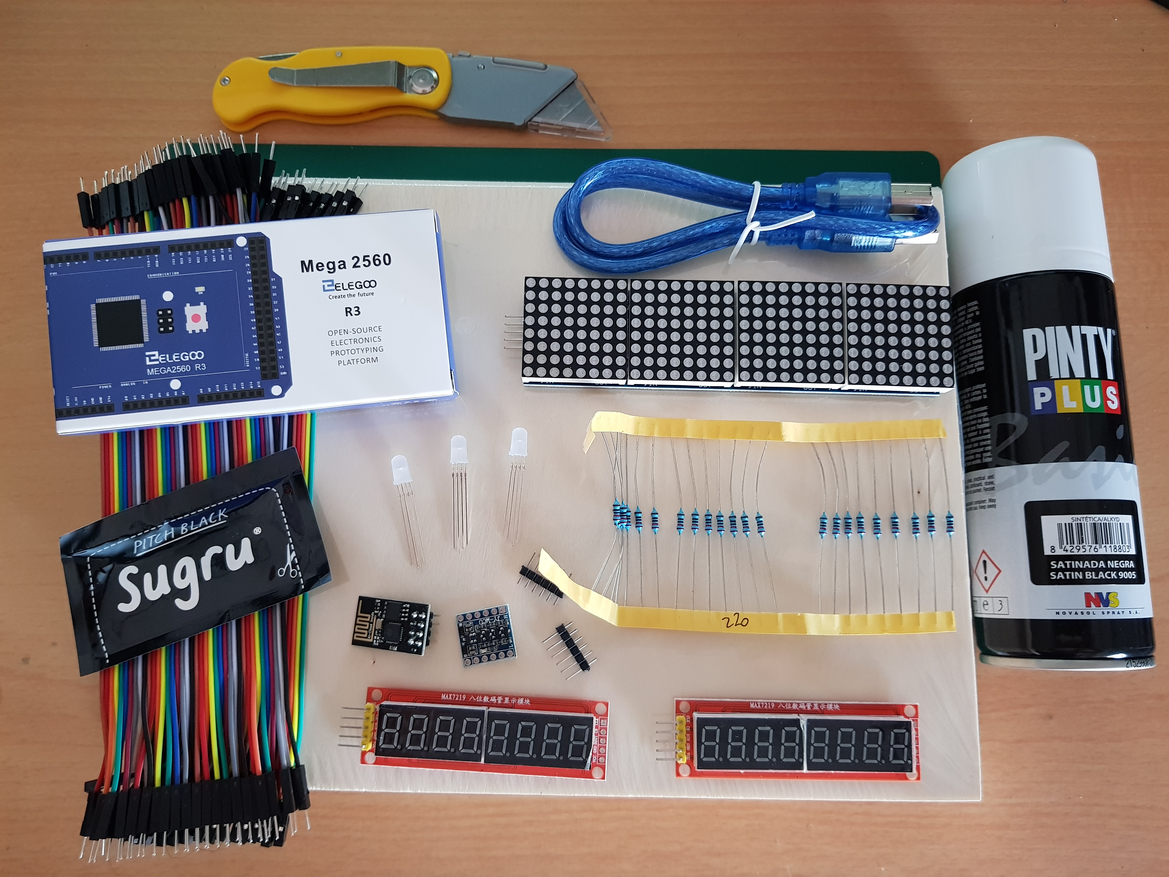
What You Will Need
1 x Wooden box (€4.50 from a local store)
1 x Arduino Mega clone – I use the Elegoo boards personally (€11.50 from Amazon)
1 x Series of 4 dot-matrix displays (€15 from Internet – though I have now seen for €5)
1 x Sugru packet (€1.65 [1 of 8 for €13 from Amazon])
2 x 7-Segment 8-Digit LED displays (€4 for 2 – or €12 next day delivery)
1 x Collection of 220 ohm resistors (€0.25 – part of pack costing €5).
3 x RGB LEDs (€0.18 – part of pack of 50 costing €3)
1 x ESP8266 chip (€5)
1 x 5v <> 3.5v level switcher (€1.50)
1 x Matt black spray paint (€2 can from a local store).
1 x Small breadboard
‘DuPont’ cables and pins – (€3 – usually part of any starter pack)
Access to a drill, box cutter, USB cable
Cost is therefore around €50 – although existing parts could be reused, and ordering through Aliexpress for example would bring that down to nearer €30.
The project takes 4 – 8 hours to complete, including waiting for the box to dry.
Preparing the RGB LEDs
Preparing the RGB LEDs (Red-Green-Blue Light-Emitting-Diodes) is quite time consuming, but satisfying once it is completed. I am using RGB LEDs to enable me to show different colours using the ‘same’ LED. In reality these RGB LEDs contain 3 LEDs inside and by controlling each light you can get a mix of colour.
Each LED needs a resistor in circuit, I use 220 ohm resistors with my LEDs and have never had a problem. Other tutorials may suggest different values, use whatever resistors you want, but do remember to include them, otherwise you will burn out your LEDs.

I won’t go into too much depth about LEDs as tutorials such as this one have covered the subject perfectly.
What you need to do is solder a resistor to each of the three shorter legs of your RGB LED. I like to use a ‘helping hands’ device such as this one. Firstly wrap the wires together, then solder the connection, wait 30 seconds or so and you should find the wires are strongly attached to each other. Eventually you will want to cover the connection with insulating tape or heat shrink tubing.
In the second picture you can see my three RGB LEDs, after I have soldered three resistors and then further wires which will go to the Arduino. Additionally I have soldered a wire to the common pin, which returns to the ground rail.
At this point you will want to connect the LEDs to your Arduino and test that they work. I would recommend following any RGB LED tutorial and cycling through the colours to check that your LEDs are performing as you wish.
In my case I noticed that the green LED was much brighter than the red LED. This seems to be fairly common. If this is a problem then you might consider a larger value resistor for the green LED.
Once you have 3 RGB LEDs that you can control and that successfully show red, green and blue, then continue to the next step.
Preparing LED Dot-matrix and 7-Segment Displays
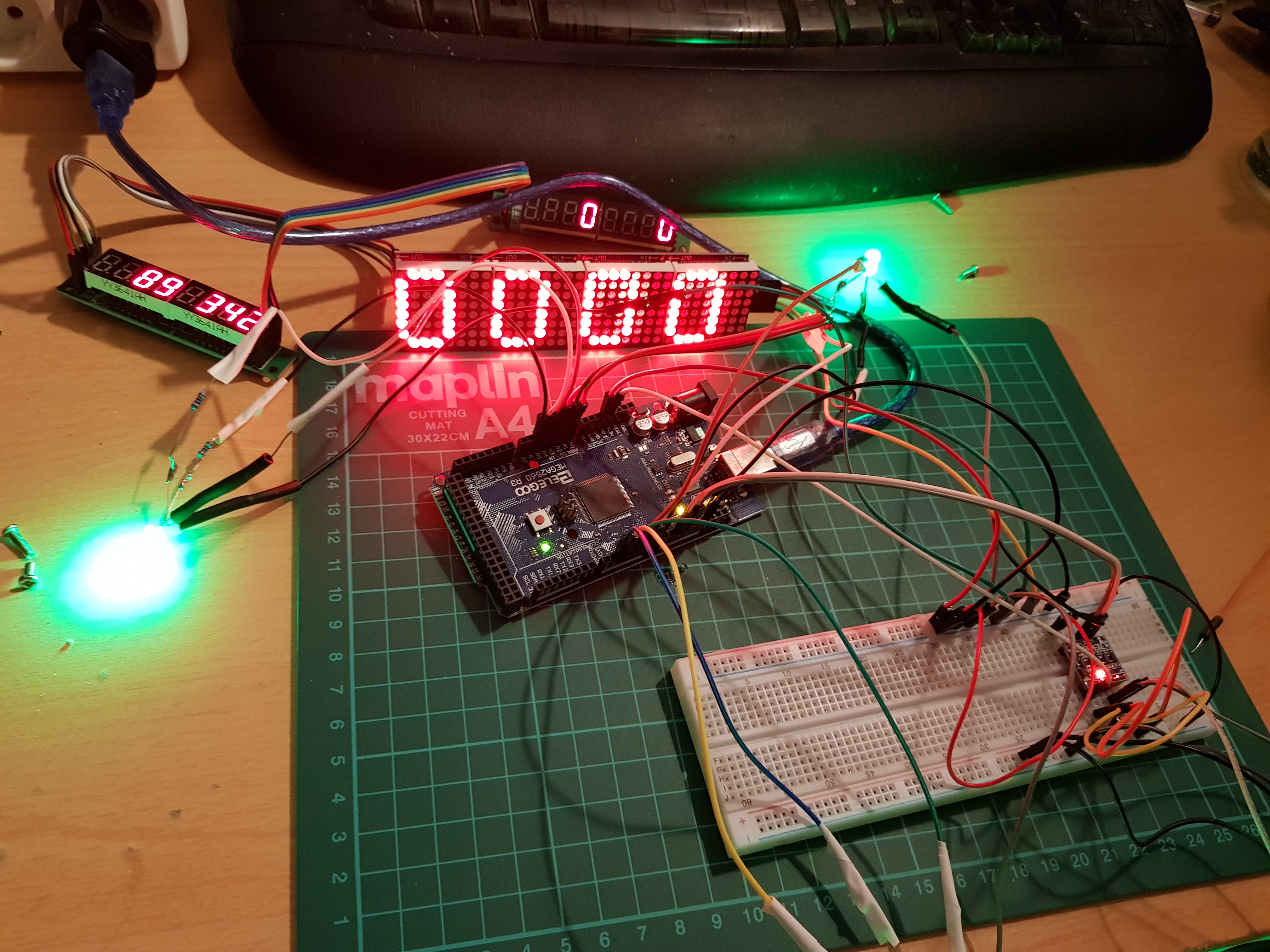
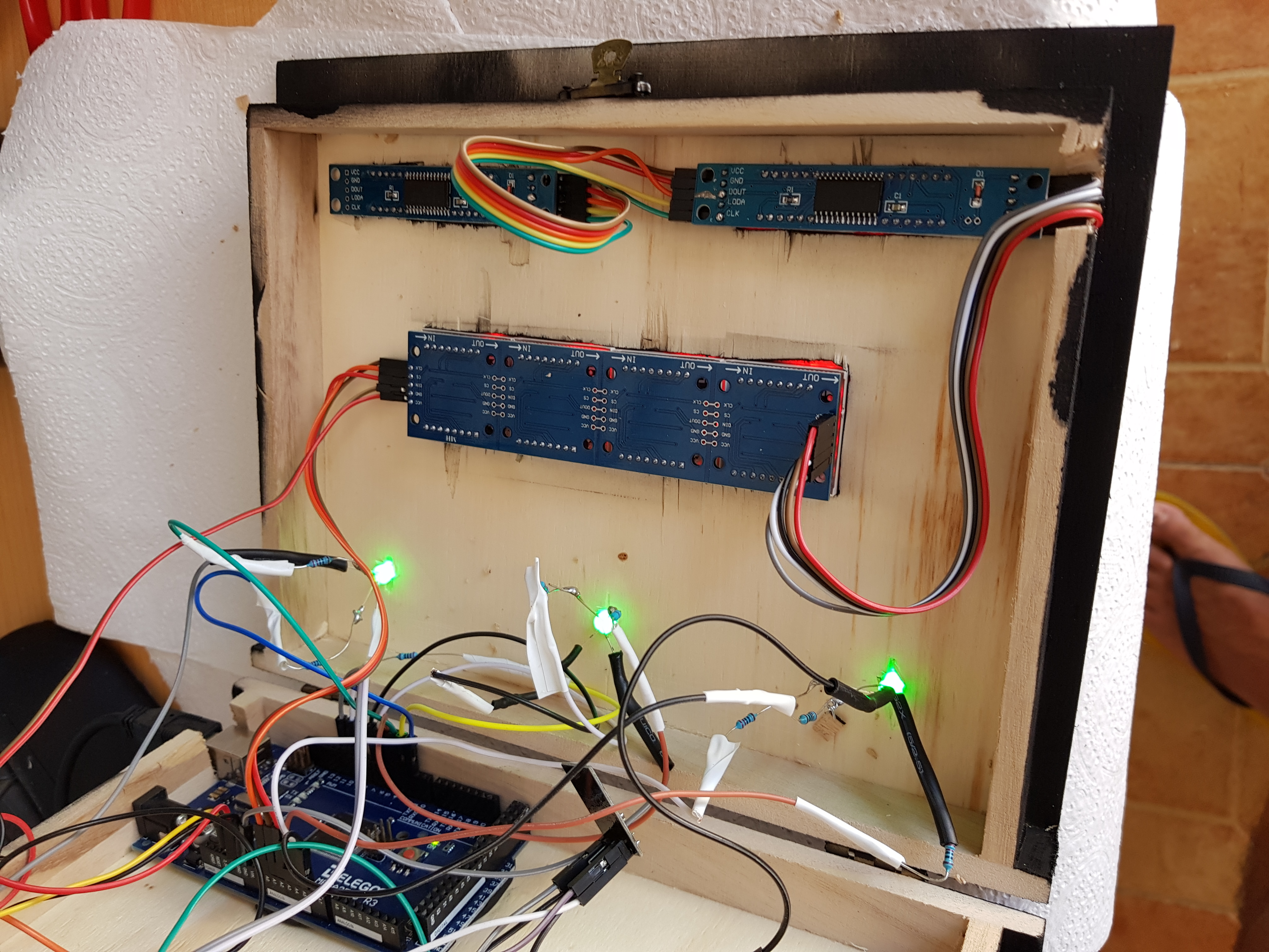
While showing green/red LEDs is useful for displaying boolean information such as true/false, on/off, yes/no, for our scoreboard to be really interesting we are going to want to display some numbers. I am going to use two different components to show information, they are related to such a degree that we can actually wire them in sequence, and use a very minimal number of pins on our Arduino board.
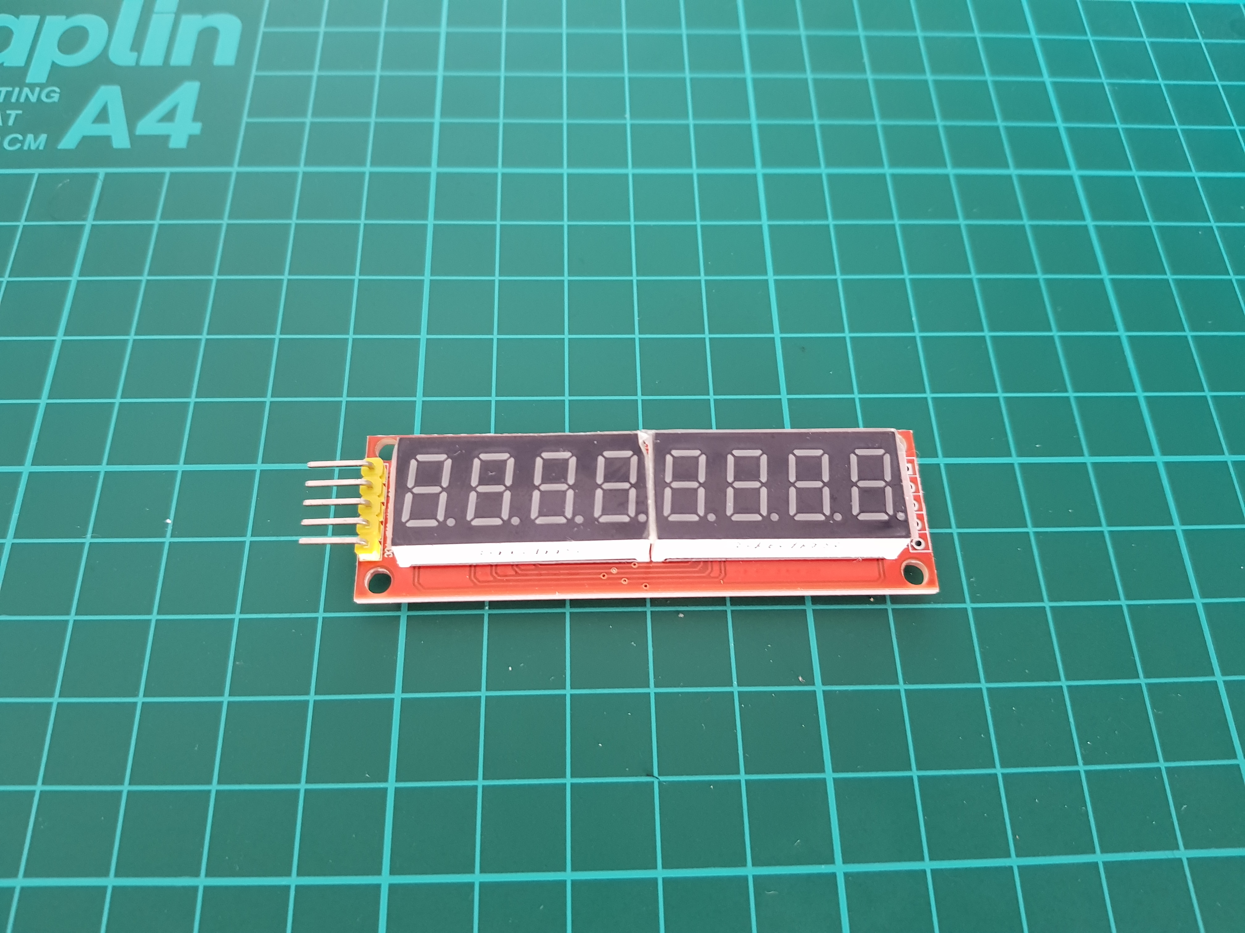
The 8 digit display shown in the picture is similar to this one – these are extremely common in Arduino starter packs and while colours vary pretty much all use the MAX7219 component which allows use to set all 8 digits using just 5 pins. Without the MAX7219 component we’d need a huge number of pins and resistors to set each 7-segment digit, and that would take forever and use most if not all our Arduino pins. Another benefit of this design of 7-segment 8-digit display is that they can be daisy chained, meaning you can have up to 8 of them in sequence, again controlled by just 5 pins.
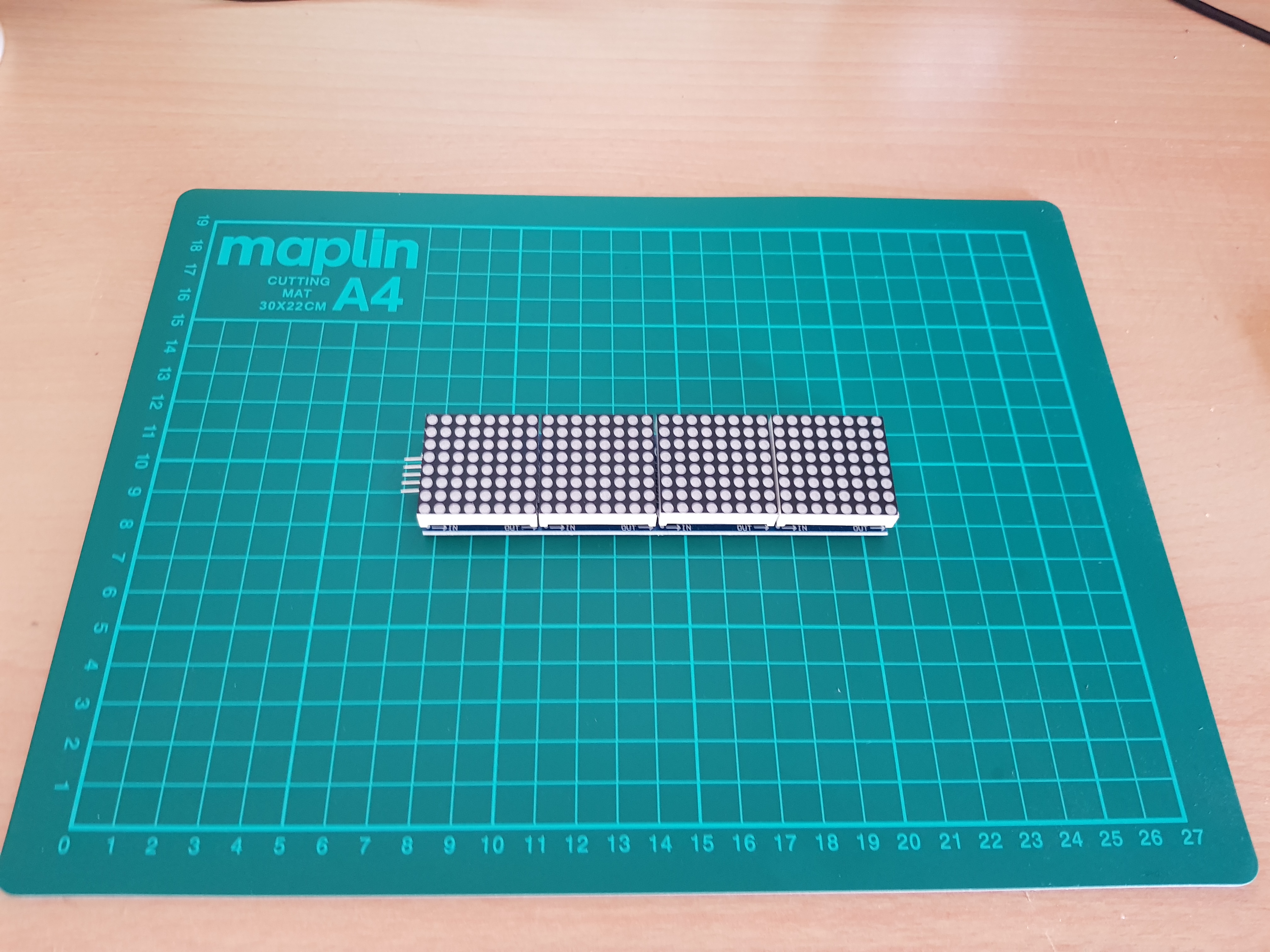
The dot-matrix display is a grid of LEDs that is in effect a low resolution display, we choose which of the dots is lit and therefore can draw simple shapes, letters and numbers. Here I’m using a special component which is four of these dot-matrix displays connected together. This gives us an 32 x 8 display, on which we can display information. This counts as 4 items in our chain of 8, so you could use two of them, or in my case mix one of these with some 7-segment displays. For this dashboard I am using two, bringing my total number of chained components to 6. All driven from 5 pins on my Arduino board, and that’s including one for 5v and one for ground. Pretty efficient I think!
I will delve into the code required to drive these components, and display useful information, in a later step. For now, ensure that the components are wired to your Arduino board and perhaps follow any simple tutorial (of which there are many) to be sure that your components are working.
Preparing Our Enclosure
To look the part our device needs to sit comfortably in an enclosure, where it can live and look like a piece of consumer electronics, rather than a science fair project. Most modern day devices, such as televisions, mobile phones and Blu-ray players use plastic enclosures due to its lightweight nature and consistent form. We are going to use wood, which is heavier and more brittle, but for our needs will work perfectly well.
I have searched the Internet and endless DIY stores for the perfect project box. In the end I found the perfect project box in a ‘Chinese bazaar shop’ here in Spain. These are universally run by Chinese people (hence the name) and stock a huge range of products, pretty much all imported from China. They are a goldmine for useful items. Eventually I found one that stocked such a huge range of boxes that one was the perfect fit for my scoreboard project. The price was also excellent, coming in at just €4.50.
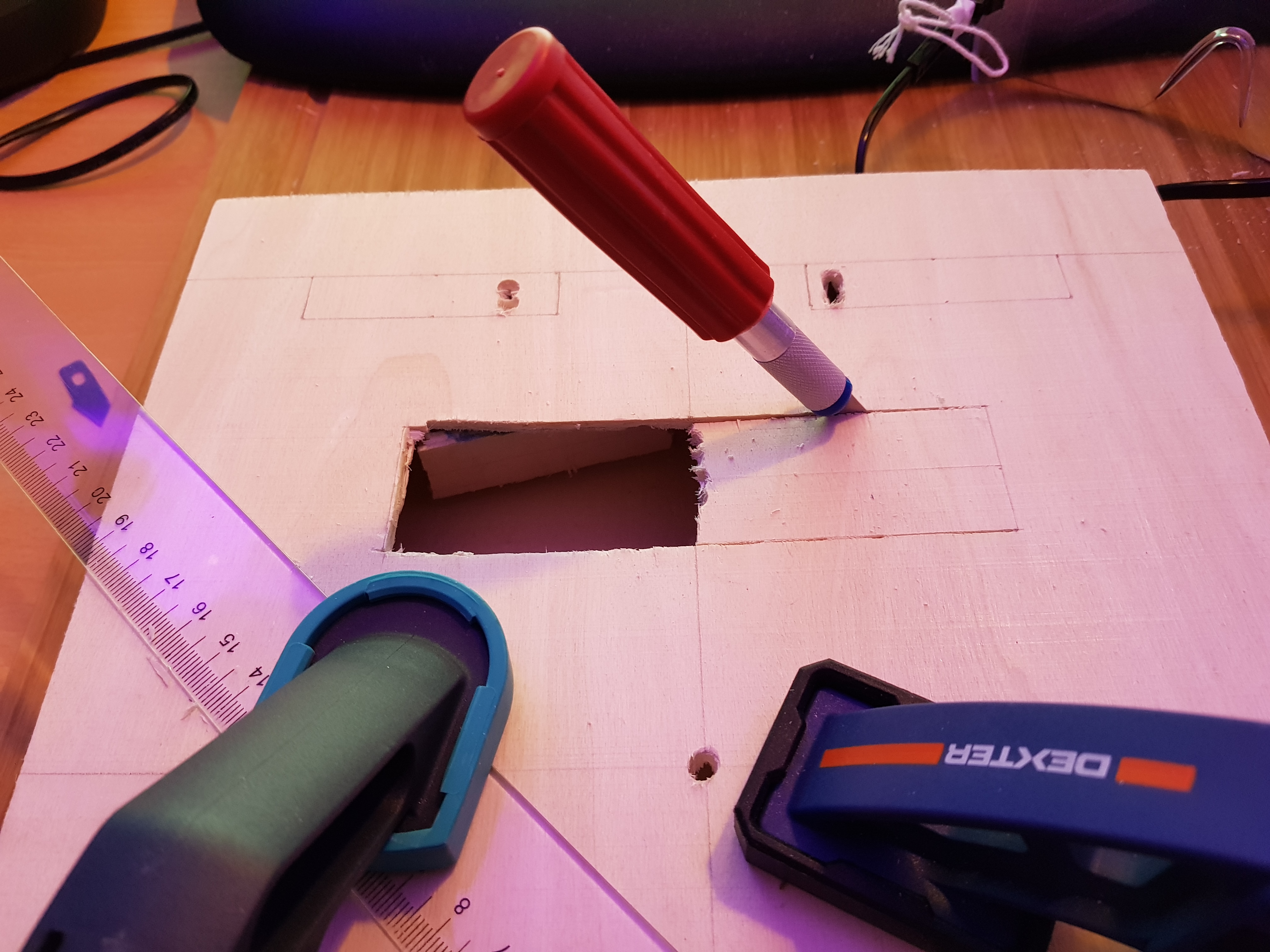
The box is made from plywood, meaning it’s structurally strong but also easy to cut into using a box cutter. I tried using a jigsaw machine and a saw, but in the end found that cutting windows in these boxes is best done using a simple box cutter. My box cutter set cost just €2 from the same store.
For my project I decided to have 3 RGB LEDs, evenly spaced out at the bottom of the scoreboard. I simply used a ruler to measure out evenly spaced points, then used a power drill to create a hole. I had to experiment slightly to get the right drill piece for the LEDs, you may need to create one first and then push an LED through to see that it fits snugly. Push the drill through swiftly while holding the box down using two clamps. If you don’t have access to a clamp, then a friend might do! Though I strongly recommend investing in two clamps such as these, they will easily pay for themselves over the years.
My drill was purchased for €29.99 from a typical DIY store, it’s nothing too special, you really don’t need anything other than a basic power drill for these projects. I imagine it will last me 20 years, so again, in the long run it’s very cheap.
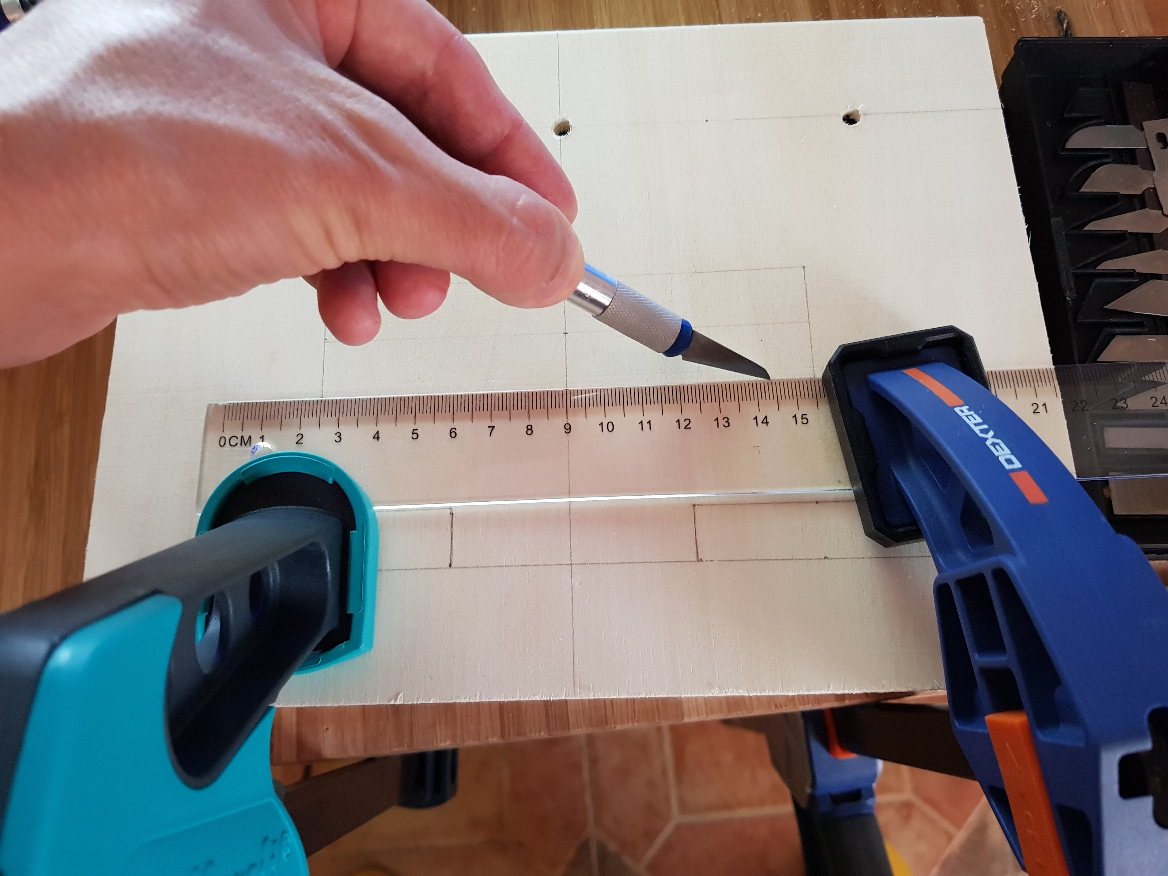
The dox-matrix display and 7-segment 8-digit components will need windows in your box. Again I used a basic ruler and pencil to measure out the sizes and draw where the windows would go on the box. Think carefully at this stage, you will want to ensure your displays are well spaced out, creating two windows in your box close together might cause the wood to break. I would recommend at least 15mm between windows, if not more.
Depending on the number of available pins on your Arduino, you could add several more windows or indeed several more holes for LEDs. The Arduino Mega compatible boards have plenty of pins available, if you are using an Arduino Uno compatible board then you will be far more limited.

At this point you will want to confirm which board you are using, as you should determine it’s location inside the box. The reason for this is that you will need to cut a hole for the USB cable and port. I recommend using the USB port for the power as then you will be able to connect to a computer when needed to easily upload new firmware to your device. Using the barrel power socket has minimal advantages and you would still need some way to access the USB port or internal serial pins to upload new firmware. So all in all when using an Uno or Mega compatible board, I highly recommend cutting a hole for the USB port and leaving it at that.
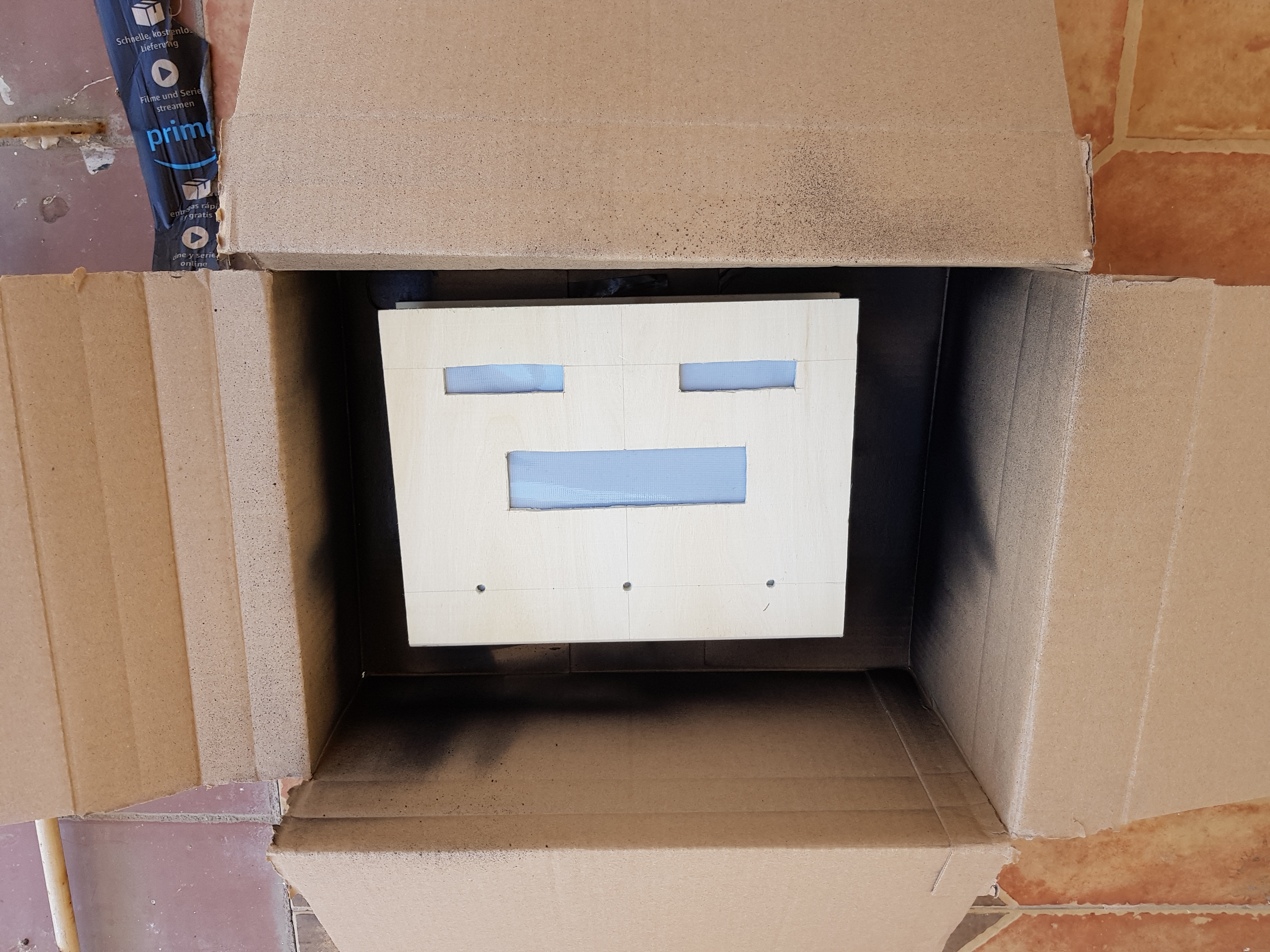
The next stage is to paint your box. I used some cheap spray paint that I was able to buy for just €2 a can. This will last you several projects, and so the cost per project is much lower. Place your box inside a larger cardboard box and take it outside, carefully spray the box, wait 30 minutes or so, then carefully turn it over if it seems to have dried. Spray the rest of the box. You may want to wait a couple of hours for the box to dry before giving it a second layer of paint. Waiting for the box to dry is boring and so perhaps work on the software side of the project while it is drying.
Eventually you will have a very smart looking box, with correctly sized windows for your components, and a small exit on the side for the USB port of your Arduino compatible board.
Mounting Your Components
After many experiments with screws and mounting sockets, tape and glue, I discovered Sugru. I highly recommend that you save yourself many hours of messing around with drill pieces and standoffs and nails etc and just invest in some Sugru. For those who haven’t yet discovered it, it’s basically a ‘blu-tac’ style putty that you can mould in your hands, the difference being that it goes hard after a few minutes, and sticks to a huge number of surfaces, including wood and Arduino boards and components. You place a small pea sized amount on the back of your item and push it hard onto the wood, in 24 hours that connection will be solid and surprisingly tough.

Sugru isn’t cheap, far from it, but when you take into account the money saved on pots of screws and standoffs, it actually represents pretty good value for money.
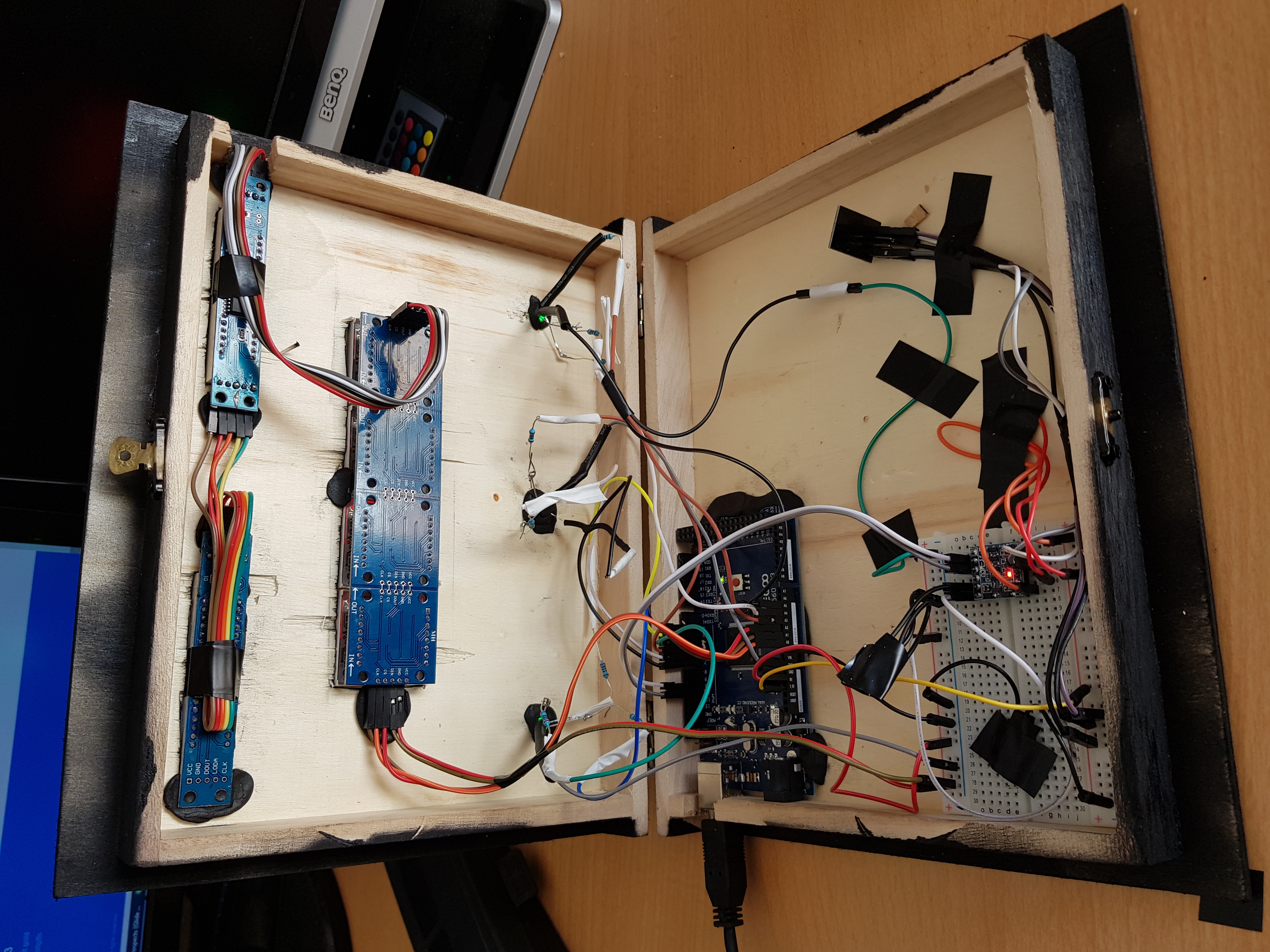
Take your Arduino compatible board and a packet of Sugru, spread the putty around a bit and place blobs of it on the underside of your board, then push the board firmly into place so that your USB port correctly lines up with the hole on the side of your box.
Now I wouldn’t recommend fixing your components into place until you are certain that they will work. As this tutorial is split into distinct sections I am going to assume that you have returned to this part after knowing that your scoreboard correctly works.
The 8-digit displays can be mounted using some Sugru on the plastic part of the connecting wire, and possibly some Sugru through any gaps between the component and your box window. Do ensure that you have them mounted the correct way up! It is safe to handle them while your device is powered up, I would suggest you do this to ensure that you place the components correctly. You can read your display while mounting it to be 100% certain it’s the right way up.
Later on in this tutorial you will see see why we are using a breadboard and two other chips. I mounted the breadboard using its sticky backing, which sticks extremely well to wood, and some tape to hold the WiFi chip to stop it moving too much.
You may wish to use hot glue to fix the wires to your breadboard, I didn’t do this but have heard that it works quite well. This may be necessary if your wires don’t sit very snugly in your breadboard.
Using the ESP8266 Chip
Our scoreboard needs to connect to the Internet to get data to display on our LED components. The Arduino Mega or Uno compatible boards do not contain on-board WiFi, and so we have to use a further component to connect our project to the Internet.
The ESP8266 chip is marvellous, at around $6 in the US, or 2 for 10 euros here in Europe it is extremely good value. It’s actually a complete SOC (system-on-a-chip) so in many ways is effectively ‘another Arduino’ style component, you can upload code to the device and use it on it’s own. In this project however we wish to use it alongside our Arduino compatible board, with information being passed from the ESP8266 chip to our central board.
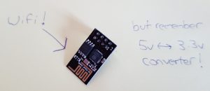
This task is more complicated than it might otherwise be due to the fact that the ESP8266 runs at 3.3v not 5v like our Arduino Mega board. This means that signals sent from the ESP8266 can’t simply be connected to digital pins on our Arduino, and we can’t power the ESP8266 from the 5v pin on our Arduino.
Fortunately we have a 3.3v pin on our Arduino which is suitable for powering the ESP8266. However, we are still left with the problem of the data pins. To solve this problem we need to use a level-converter. This small chip takes in power, ground and several communication wires and outputs the same signals having been dropped down to 3.3v. This means signals from our Arduino board get converted into a voltage that the ESP8266 board can use, and vice-versa on the return.
As this setup involves several wires and multiple connections to power pins I have used a breadboard. This allows us to mount the converter chip across the divide in the breadboard, and have the top half be our ‘5v’ zone, and the bottom half our ‘3.3v’ zone. The power rails on each side carry 5v or 3.3v, and the ground rails themselves are connected to each other and also our Arduino.
To interface with the ESP8266 chip I use a library written by Wu Pengfei – it’s two files, ESP8266.cpp and ESP8266.h. It makes connecting to the chip and making a request relatively simple.
Most of the explanation of my code comes alongside the code itself, so I won’t go into great detail during this Instructable. However in effect what we do to interface with the chip is create a complete HTTP request in a single string, connect to the web server using TCP, then send our request. We then await the response, which we place into a string, and then pull out data from the string, in a format that we already understand.
My dashboard deals with an online service that I created, your dashboard will bring in data from a different source. This could be a local web server running on your home network, or a website out on the Internet, the process is the same. If you look at roughly line 490 onwards, you’ll see how I’m doing it. My method is based upon examples I found on the Internet.
Wiring Up the Device
The adjoining diagram shows how I wire up my scoreboard. Please note: I haven’t attempted to create a perfectly reproducible dialog, this is to give you a rough overview of what I’m doing.
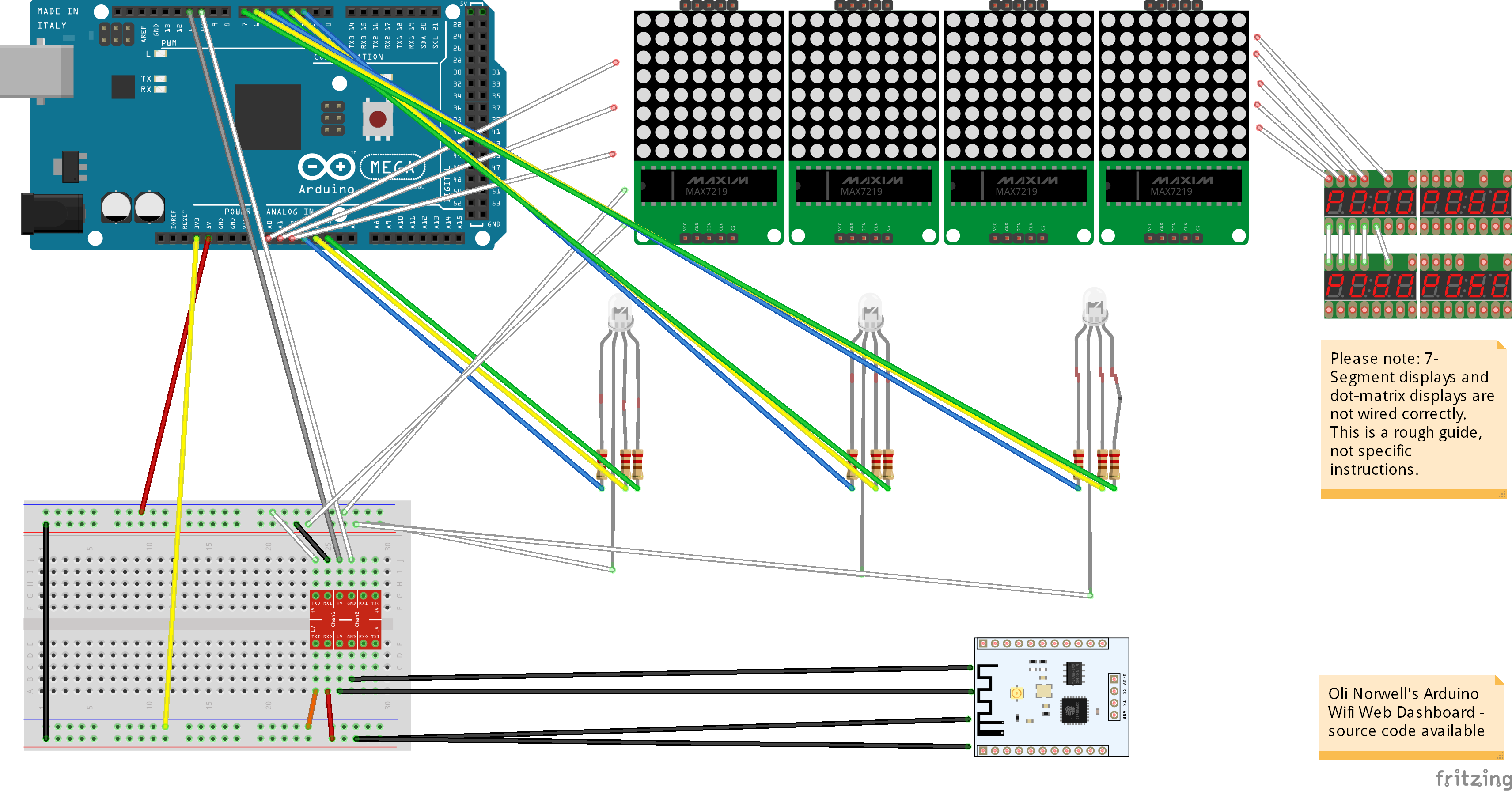
You’ll see that the wiring to the ESP8266 chip goes via the level converter which is attached to the breadboard.
Several wires are needed for each LED, as they are RGB LEDs, meaning we need a wire for R(red), G(green) and B(blue), additional we have a wire back to the ground rail.
Thankfully we can put the dot-matrix displays and 7-segment number components in series, meaning only one set of wires is needed.
Additionally you’ll see that 5v and 3.3v power wires go both to the breadboard and via the converter.
I had considered moving from a breadboard to a more permanent solution like a protoboard, but in the end, this solutions works fine for this project. If you have a good quality breadboard, and (more importantly) good quality ‘Dupont’ jumper wires, then you can go a long way.
I’ve read that some people like to cover the breadboard and wires in hot glue, which will hold it fixed. Dried hot glue isn’t a good conductor, so the circuit should be unaffected. I haven’t tried this yet but it’s certainly something to consider, additionally more Sugru could be used to hold jumper wires in place.
Software
Critical to the working of the scoreboard is of course the software running on the microprocessor chip. This needs to control the ESP8266 chip and request updated data from the Internet, then interpret that data and show it visually on our LED displays.
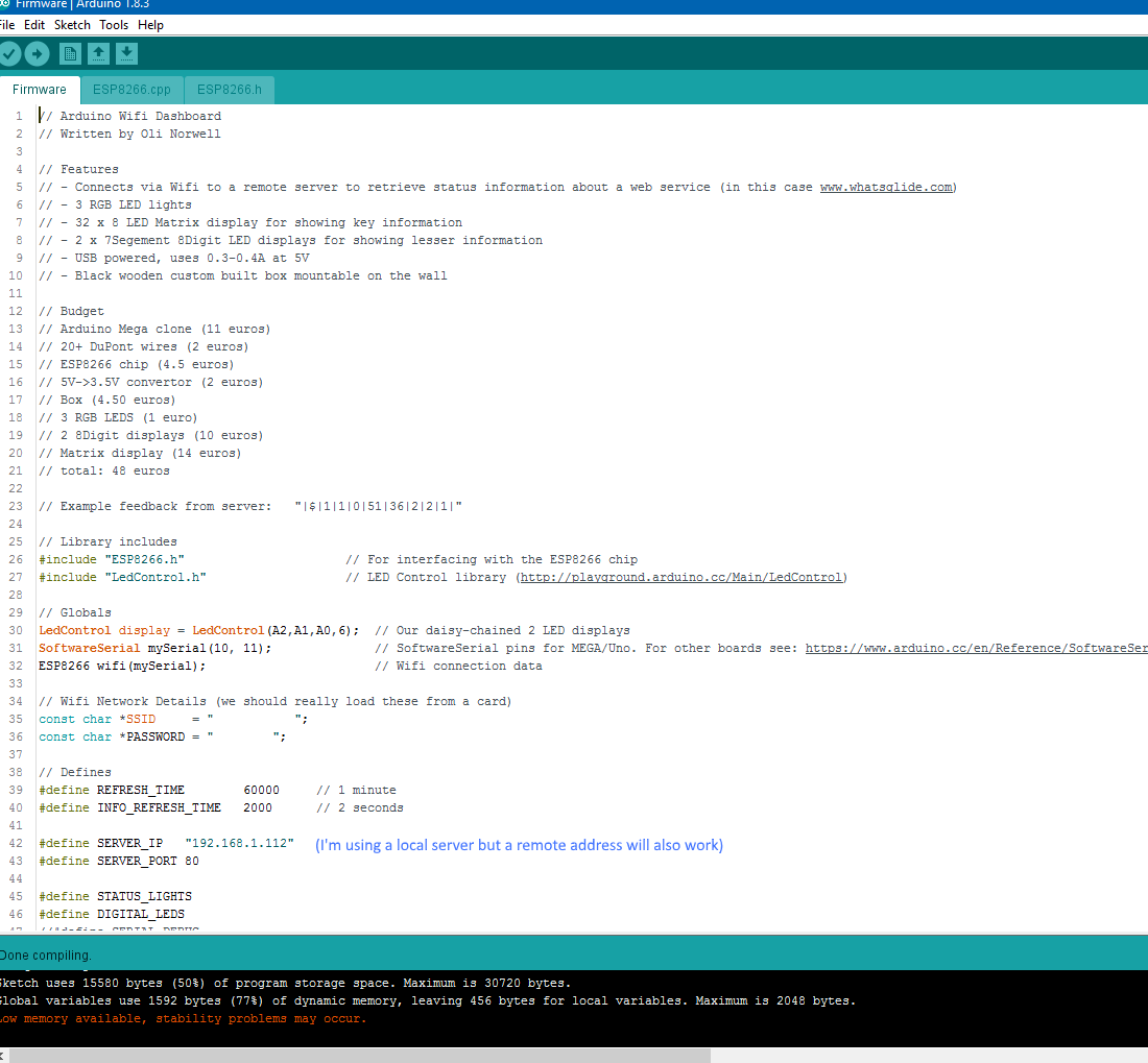
I have included full source code for my scoreboard, you will need to enter your own WiFi credentials (obviously!) and point it to a different web page. I won’t go into too much detail about the web server side of things, as this is extremely flexible, and you would need to create the relevant solution for your problem.
My page returns a very simple string, in the form: |$|1|1|0|51|36|2|2|1|
I first look for the ‘|$|’ pattern, if I see that then I can assume I’ve got the correct beginning of my string. Afterwards I move through the string, placing what I find into new strings, which then get turned into integer numbers. When I find a ‘|’ character, I know I’m onto the next one. You can see exactly how I do this in the code.
Next we have to update local variables which are being held in our dashboard. You will need a variable for each piece of information that you wish to show. In my case this is ‘server 1 okay’, ‘server 2 okay’, ‘cron task done’, ‘current users’, ‘current systems’, ‘daily users’, ‘daily systems’.
After re-fetching the page every 60 seconds, and converting the string returned from the web server into a series of numbers, I then update my dashboard with the new numbers.
For the server statuses, and cron status, this is simply a case of setting the colour of one of the LEDs. For me green means success, red means fail, and blue means there was an issue with the connection.
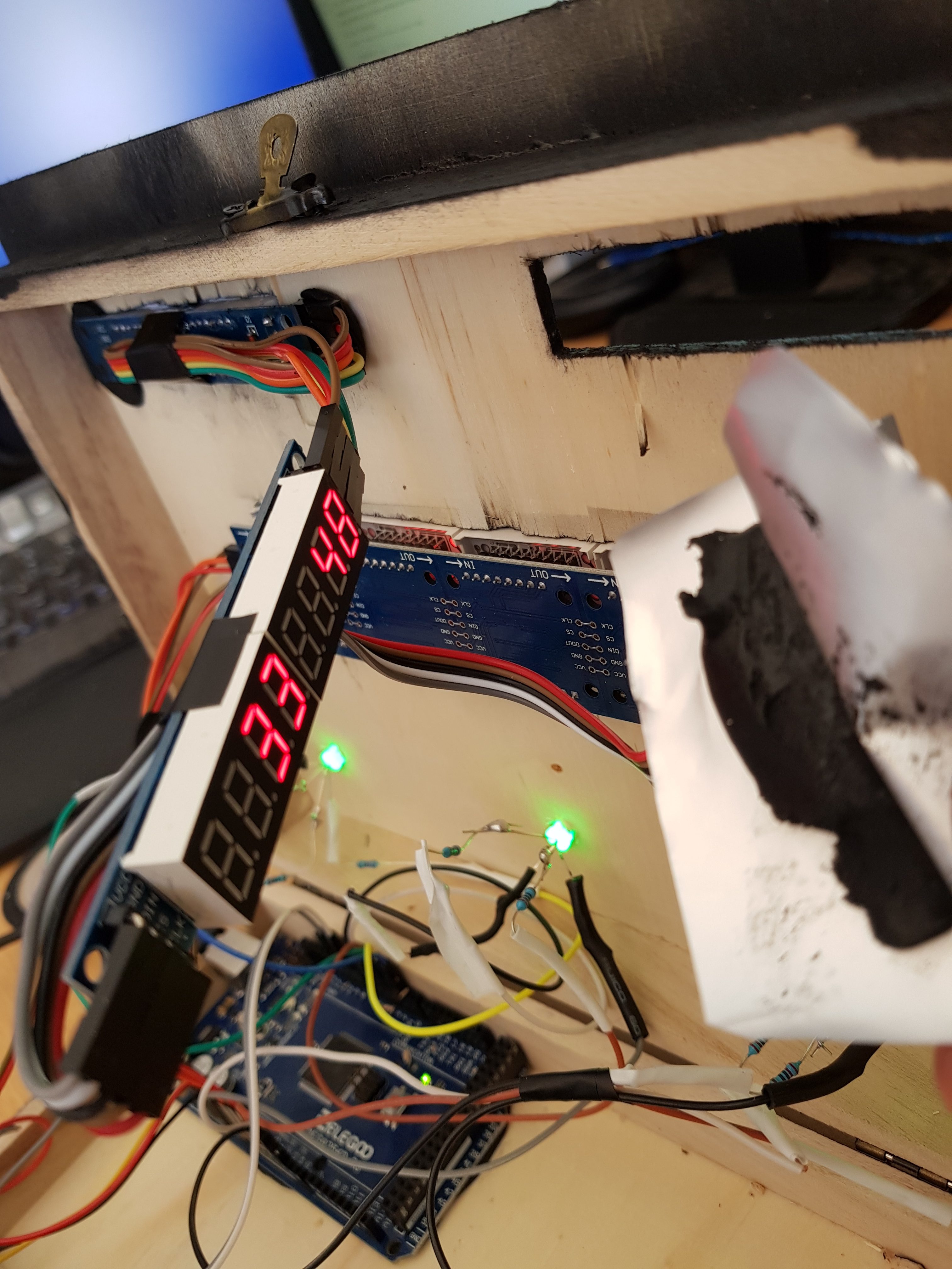
The two 7-segment 8-digit displays are both split into 4-digit segments, I then output my 4 pieces of data onto them. This is slightly more complicated than it looks, as I need to convert an integer number, to the actual digit for the 100s column, 10s column and digit column of the display. As you set each digit separately, this is necessary. You can see in the code how I approached this problem.
The central dot-matrix display shows information that changes every 2 seconds. I have a function called displayMatrix which sets one of the 4 displays to show an ‘image’ that I have stored in the IMAGES[] array. This array is interesting as it was generated by a web page rather than myself.
I highly recommend using the LED Matrix Editor, this page makes it very easy to create ‘images’ in the 8×8 format that will display correctly on your dot-matrix components. Using the page is extremely straightforward, if you click the link you will get the editor with the images from my dashboard already loaded. As you can see it’s simply a case of clicking the dots to change whether they are on or off. You can easily add more images, or move the order by dragging and dropping. After making your changes, bookmark the page to be able to return to them.
In the top corner of the editor you will see the definition in code for your images. Copy and paste this into your Arduino ‘sketch’. Look at the code for the displayMatrix function to see how it loops through the values to set the relevant LED in the component.
This pretty much sums up the code for my dashboard, further explanation is available in the source code itself. If you have any questions at all please ask them in the comments.
Further Ideas and Project Summary
I hope you have enjoyed reading through this tutorial, and that you are able to successfully build your own Arduino WiFi scoreboard. I think what is great about this particular project is that it could be customised in so many ways. I had a need to report live user data from a web service, your needs are likely to be very different.
Some ideas for scoreboards that I have had include:
A sports scoreboard showing current scores, perhaps useful for a school sports tournament.
A live Bitcoin price monitor, including traditional currency conversion rates as well, and perhaps stock market values.
A live weather scoreboard, showing temperatures in various cities, perhaps cycling through dozens of cities displaying one per second.
A live YouTube subscriber count
Real sports scores pulled from a live sports site such as Livescores.com or something like ESPN.
The possibilities are endless. I wish you best of luck with your projects. Please leave any comments below.
(I’ve also posted this to Arduino, Instructables, Hackster.io)
Hello, I can’t seem to find the source code for the project attached. I was wondering if you still had the original source code for me to look at? Thank you.