Last updated on October 19, 2024
This guide will walk you through building a USB gear stick / shifter that will work with any PC racing game. I have deliberately stuck to building the simplest possible version of the device in the hope that those out there wanting to build one can do so in the shortest time possible.
(a YouTube video of the finished product in action is at the bottom of this post)
What you will need
- A wooden chopping board of reasonable thickness (€1.20)
- MDF of the same size as the chopping board (€0.50)
- An Arduino Leonardo compatible board (€4 on AliExpress)
- An arcade style 4-direction joystick (about €7 on AliExpress)
- 140cm M8 threaded rod (€0.80)
- 30cm M5* threaded rod (€0.50)
- M8 nuts and washers (€1)
- M5* nuts and washers (€1)
- 4 (or more) M8 cap nuts (€1)
- 10 male to male ‘du-pont cables’ (€0.20)
- A collection of magnets (€7)
- 2 x tripod size conversion blocks (€3)
- 6 ‘L’ shaped brackets (€3)
- A small breadboard (optional)
- Long USB lead (€2)
(* size of rod depends on your joystick mounting holes)
Total cost: Around $30/€30/£30
Time to build: 2-6 hours
The basic concept
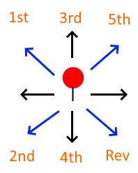
We’re going to be using an arcade style joystick as the basis for our gear stick. Now you’re probably thinking, how can we make a 7 position shifter (N-1-2-3-4-5-R) with a device that can only go in 4 directions? The joystick is not analog and works by directional switches being pushed or not.
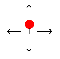
The answer is that the joystick will let us push it diagonally, which involves more than one joystick switch being selected. So for example when pushing it to the top-left, both the left and the up switches are set.
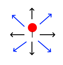
We can then implement a lookup table to decide what gear we are in based on how the 4 switches are set.
Writing the software
A very useful feature of our Leonardo board is that it can be programmed to work as a keyboard, mouse or joystick. That is we can program the device’s memory so that when the device is plugged into a computer, the computer ‘sees’ either a mouse, keyboard or joystick, rather than a microcontroller development board.
The software we need to write is actually extremely simple. We will be reading whether the 4 switches on the joystick are pressed or not, and then depending on which are pressed, we can calculate what gear we are in. We can then pass that message on to the computer, which will pass it on to our game.
You can download the source code here. It’s also on Github.
// Gear Stick / H-shifter firmware for Arduino Leonardo compatible devices
// Written by Oli Norwell (www.olinorwell.com) - 11 July 2020
// The following code is released into the public domain with no warranty implied or otherwise

#include <Joystick.h>                 // Download library from https://github.com/MHeironimus/ArduinoJoystickLibrary

//#define DEBUG                       // Remove the comment '//' to enable debug mode - which will
                                      // output data into the serial console and disable the joystick functionality

Joystick_ Joystick;                   // Our joystick object - (read more at https://github.com/MHeironimus/ArduinoJoystickLibrary )

char dir_pins[] = { 8,9,10,11 };      // Our directional switches are connected to Ground and also a pin on the Leonardo [LEFT,DOWN,RIGHT,UP]
                                      // Note: due to how the joystick works, the relevant switches to connect to are opposite the location
                                      // So for example connect LEFT/pin 8 to the switch that is on the right of your joystick
                                      // Use the debug mode to see if you have wired it correctly

int dir_states[4];                    // The state of the 4 switches during this frame   (1/HIGH = not pressed,  0/LOW = pressed)
int curGear = 0;                      // The current gear that we are in
int lastGear = 0;                     // The gear that we were in during the last frame (to detect a change)
long lastChange[4];                   // The time when we last changed the state of our 4 switches (needed for debouncing)

void setup()                          // Our setup function - ran once when the device starts up
{

#ifndef DEBUG                         // If the #define DEBUG line at the top is commented out, then this runs
Joystick.begin();                     // Begin the joystick library
#endif

#ifdef DEBUG                          // If the #define DEBUG line at the top is not commented out, then this runs
Serial.begin(9600);                   // This starts up the Arduino Serial communications, which we use to send info messages to the computer
#endif

for(int a = 0; a < 4; a++)            // We have 4 pins that we are using to read the 4 switches on our joystick/gear stick [0,1,2,3]
{
  pinMode(dir_pins[a], INPUT_PULLUP); // Set them to be INPUT_PULLUP - which means that by default they will be connected to HIGH/5V
  dir_states[a] = HIGH;               // As we know that by default the pins are HIGH - we set our current states to be HIGH
  lastChange[a] = 0;                  // Set to 0 the lastChange values for each pin
}

return;
}

void loop()                           // Our loop function - after the setup function, this runs then repeats forever
{

for(int a = 0; a < 4; a++)            // For each switch read the pin value to see if the direction is pressed
{                                     // Remember when pressed it gets pulled to Ground/LOW.

  int butState = digitalRead(dir_pins[a]);  // Read the pin value

  if(butState != dir_states[a] && millis() - lastChange[a] > 50) // If it is different that the current value we have for it
  {                                                              // *** and *** it is over 50ms since we last changed it

      #ifdef DEBUG                   // This debug message is commented out - uncomment it to see in the serial monitor when
  //   Serial.println("PRESS");      // each directional switch is being pressed - this is useful to see if your wiring is
  //   Serial.println(a);            // correct
      #endif


        lastChange[a] = millis();    // Set the moment that we last changed it to the current milisecond counter
        dir_states[a] = butState;    // Update the state of the directional switch to what we just read
  }
}

lastGear = curGear;                  // On each loop there is the possibility of our gear changing, to know if it has
                                     // changed we need to remember what is was previously

// So now depending on the combinations on directional switches we can choose the gear we are in
// 0 = left  1 = down   2 = right  3 = up
if(dir_states[0] == LOW && dir_states[3] == LOW) curGear = 1;         // If left and up are pressed, then that's first gear
else if(dir_states[0] == LOW && dir_states[1] == LOW) curGear = 2;    // Left and down means 2nd gear
else if(dir_states[0] == HIGH && dir_states[2] == HIGH && dir_states[3] == LOW) curGear = 3; // If just up is pressed, that's 3rd
else if(dir_states[0] == HIGH && dir_states[2] == HIGH && dir_states[1] == LOW) curGear = 4; // If just down is pressed, that's 4th
else if(dir_states[2] == LOW && dir_states[3] == LOW) curGear = 5; // If right and up are pressed, then that's 5th
else if(dir_states[2] == LOW && dir_states[1] == LOW) curGear = 6; // If right and down are pressed, then that's reverse/6th
else curGear = 0;

// If the current gear we are in is now different than the last frame, then we need to tell the computer
if(curGear != lastGear)
{

// If the DEBUG symbol isn't defined then that means that we aren't in our debug mode, so send joystick mesasges
#ifndef DEBUG
  // Depending on what gear we are currently in, we firstly ensure all the other buttons are released
  // we do this as it makes no sense that you could be in multiple gears at the same time, so we ensure this can't happen
  // We then send a message to 'press' one of our 7 virtual joystick button, which represent the gears including reverse, and neutral

  if(curGear == 1) { for(int a = 0; a < 7; a++) Joystick.releaseButton(a); Joystick.pressButton(0); }
  else if(curGear == 2) { for(int a = 0; a < 7; a++) Joystick.releaseButton(a); Joystick.pressButton(1); }
  else if(curGear == 3) { for(int a = 0; a < 7; a++) Joystick.releaseButton(a); Joystick.pressButton(2); }
  else if(curGear == 4) { for(int a = 0; a < 7; a++) Joystick.releaseButton(a); Joystick.pressButton(3); }
  else if(curGear == 5) { for(int a = 0; a < 7; a++) Joystick.releaseButton(a); Joystick.pressButton(4); }
  else if(curGear == 6) { for(int a = 0; a < 7; a++) Joystick.releaseButton(a); Joystick.pressButton(5); }
  else if(curGear == 0) { for(int a = 0; a < 7; a++) Joystick.releaseButton(a); Joystick.pressButton(6); }

  // Note: Whether we should be pressing a button for neutral is an interesting topic - some games set the gear to neutral
  // when no other gears are set, others don't. Depending on the game you will either want to link button '6' to neutral or not

#endif

// If we have our debug mode set, then rather than send a joystick command we simply send a message via the serial interface
// If using the Arduino IDE then this can be read by going to Tools->Serial Monitor
#ifdef DEBUG
  if(curGear == 1) { Serial.println("1st gear"); }
  else if(curGear == 2) { Serial.println("2nd gear"); }
  else if(curGear == 3) { Serial.println("3rd gear"); }
  else if(curGear == 4) { Serial.println("4th gear"); }
  else if(curGear == 5) { Serial.println("5th gear"); }
  else if(curGear == 6) { Serial.println("Reverse"); }
  else if(curGear == 0) { Serial.println("Neutral"); }
#endif

}

// We then run this function again, endlessly, while our device is powered on

  return;
}
This guide won’t cover how to get the software onto the Leonardo device. There are plenty of tutorials covering that on the Internet. Compile then upload the software. When the DEBUG define is enabled the software will output messages to the serial monitor rather than behave as a joystick. You can use this mode to easily test whether the wiring of your gear stick / H-shifter is working correctly
The build
Building the gear stick will probably take an entire afternoon or longer, depending on what access you have to power tools. As you can see I purchased the bottom part of the gear stick very cheaply from a local home supplies store. The other items were mostly purchased from a local DIY store. The only items that you will need to order online are the Leonardo board and joystick module. You can opt to purchase them very cheaply directly from China via AliExpress or a similar website, or if the 3-4 week delivery timescale is too long for you, both items are also available on Amazon.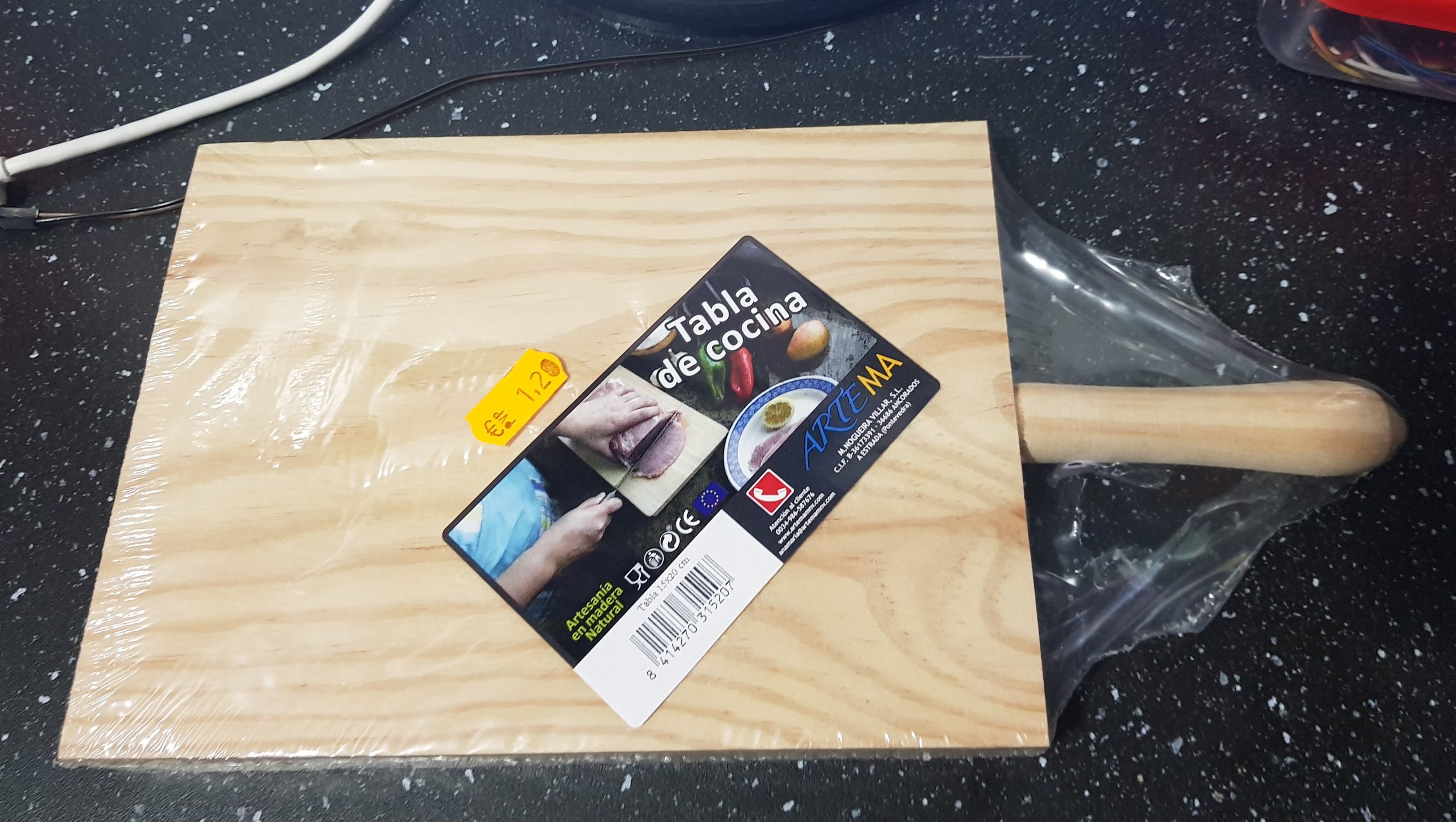
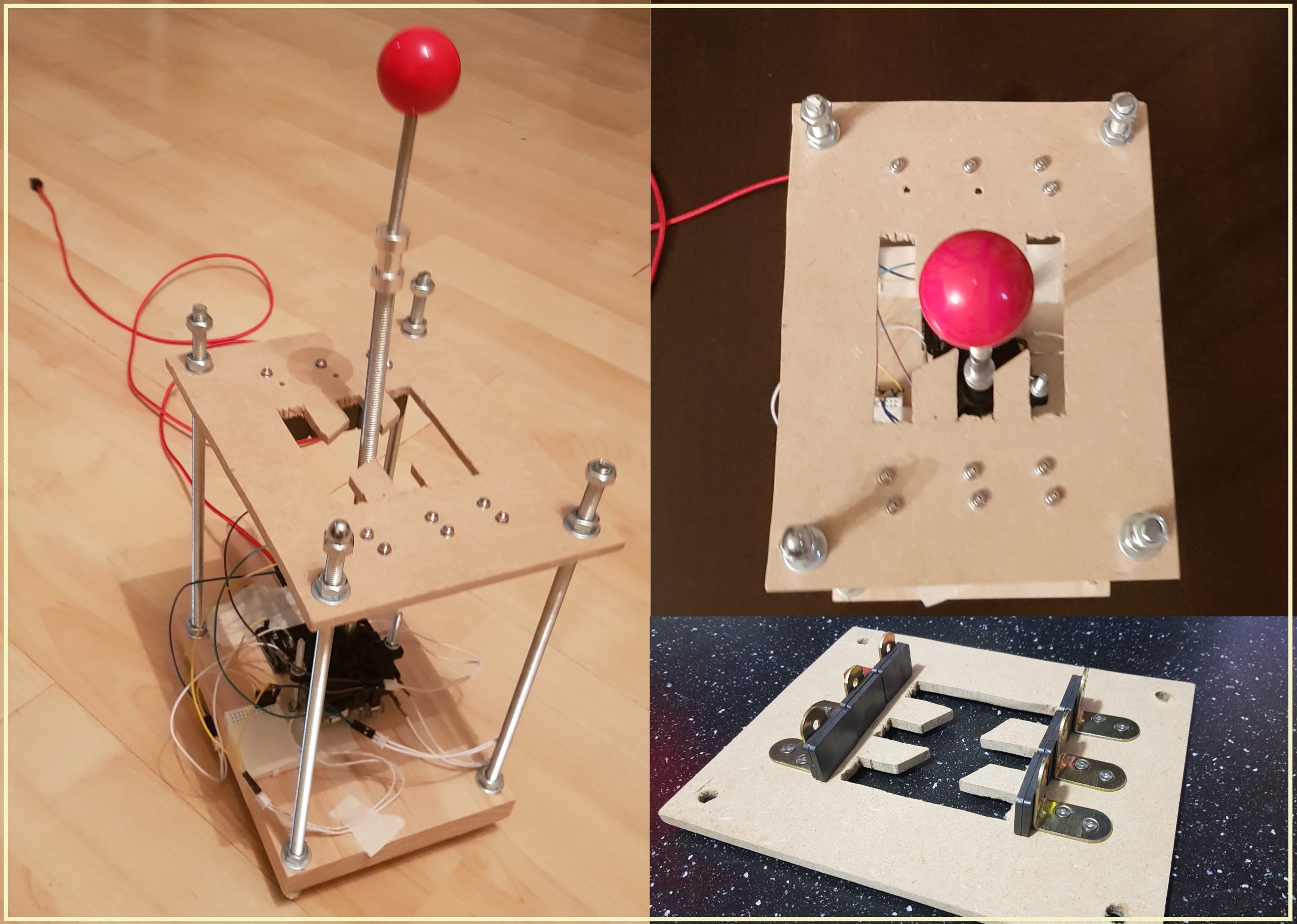
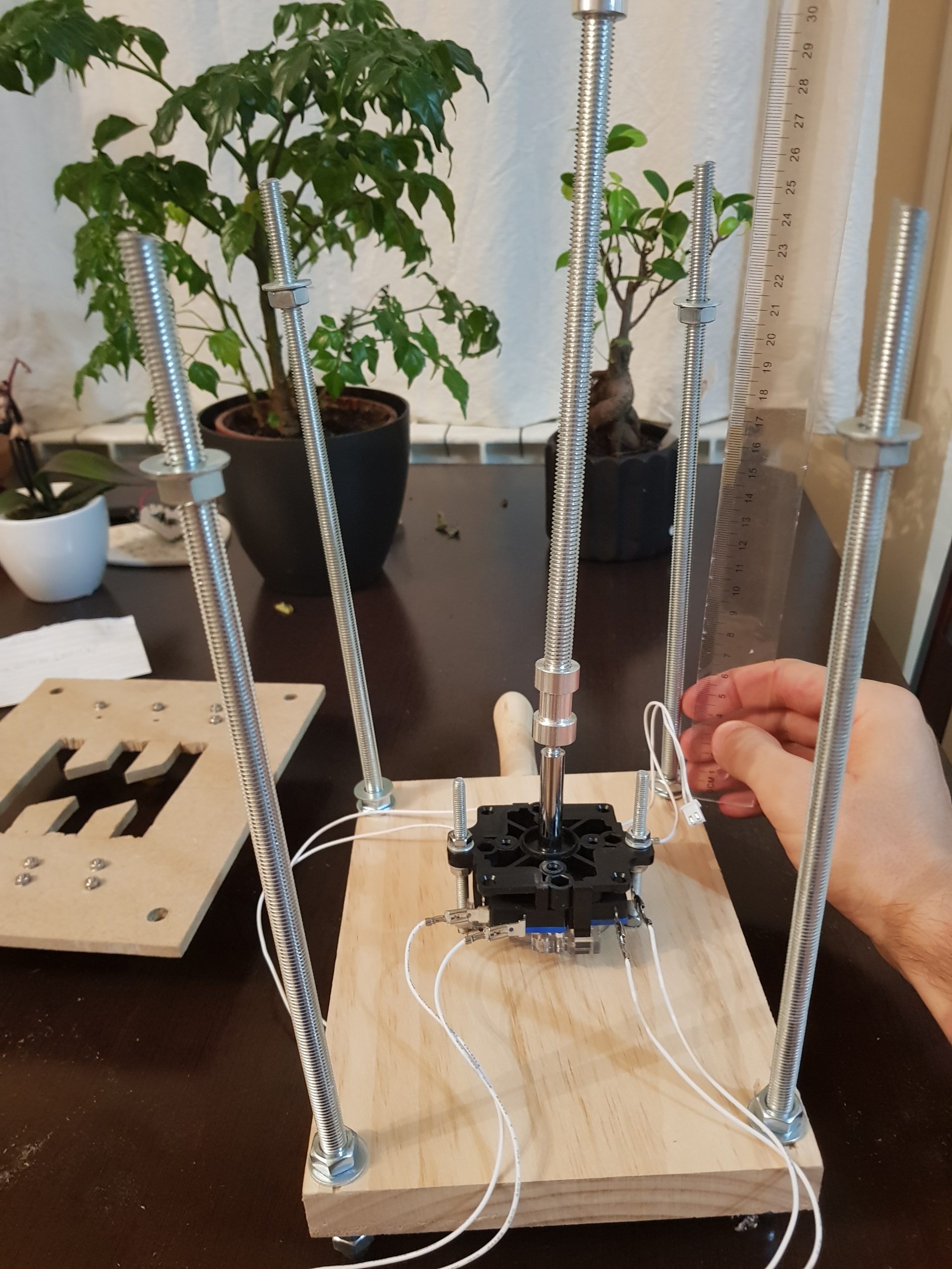
Firstly – you need to mount your joystick to your chopping board. Getting it straight vertically is very important, depending on your particular joystick module your mounting holes might be in different locations. I marked out the two mounting holes and then used threaded rod that I had of the correct size, with nuts and washers to mount the joystick. You want to ensure the joystick stands above the chopping board and can perform a full range of motion. Don’t worry about the nuts on the underneath of the board, we will have our four larger corner mounts sticking out further and they will have cap nuts on them.
Next – you should cut out a section of MDF to the size of your chopping board. Then measure four points, one in each corner, that are 1.5cm from the edge. Do the same on your chopping board. We will use threaded rod to connect the chopping board/base to the top platform on which your H pattern will be cut.
Then use a size 8 drill to cut the holes in both pieces of wood. Be careful to ensure you get the holes accurately drilled. It is worth double checking and taking time to do this well.
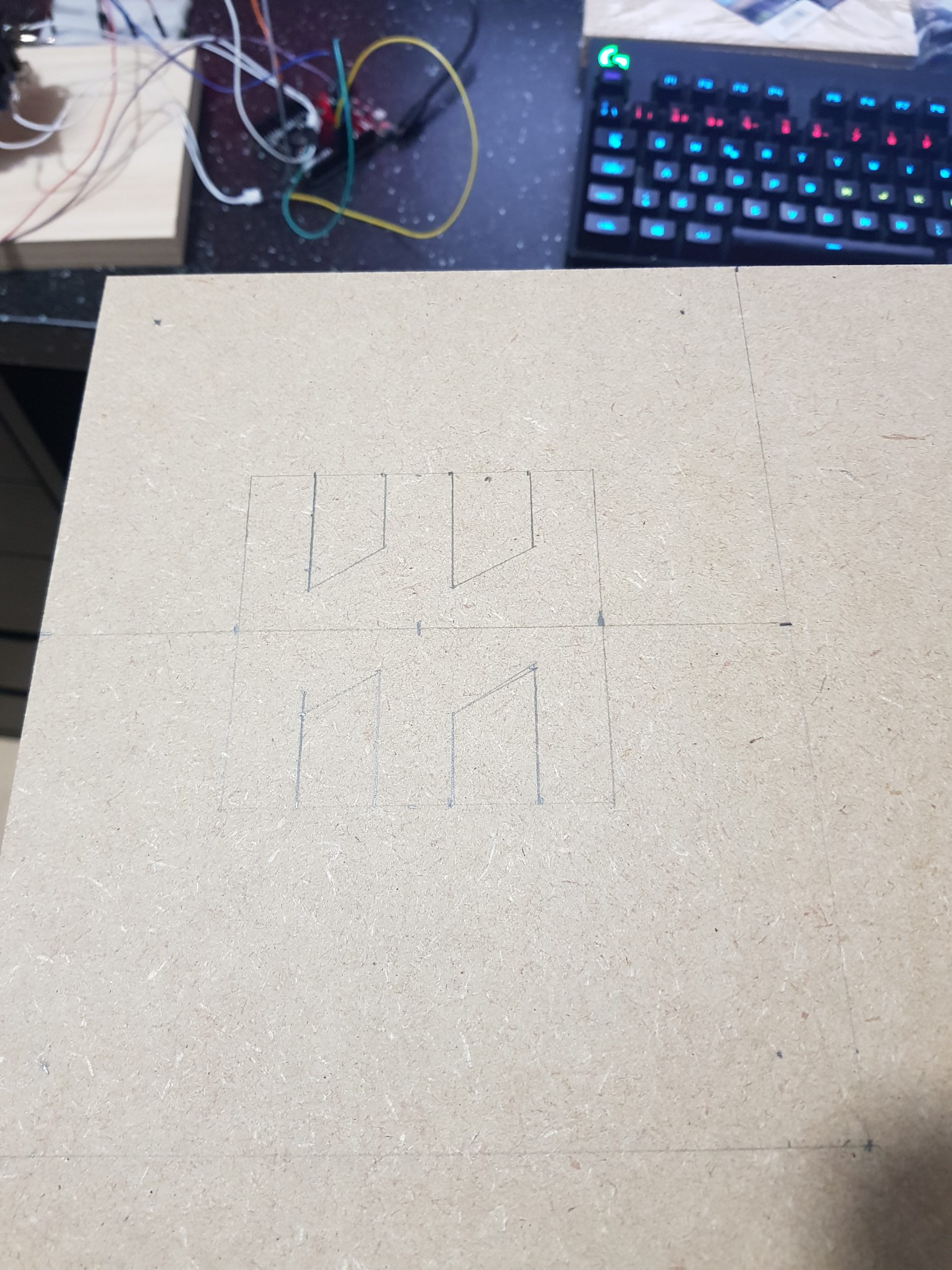
On the piece of MDF you now need to mark out the H pattern for your gear selection. Exactly what size of H pattern you’ll need depends on how high you want your gear shifter. This will depend on whether you are sitting low down on a Playseat Challenge style setup like me, or if you are sat at a chair. I suggest you take the time to work out where your gear stick is to go, and what height it would ideally be. You can then manipulate the height of the joystick and the top part of the construction, to best fit your situation.
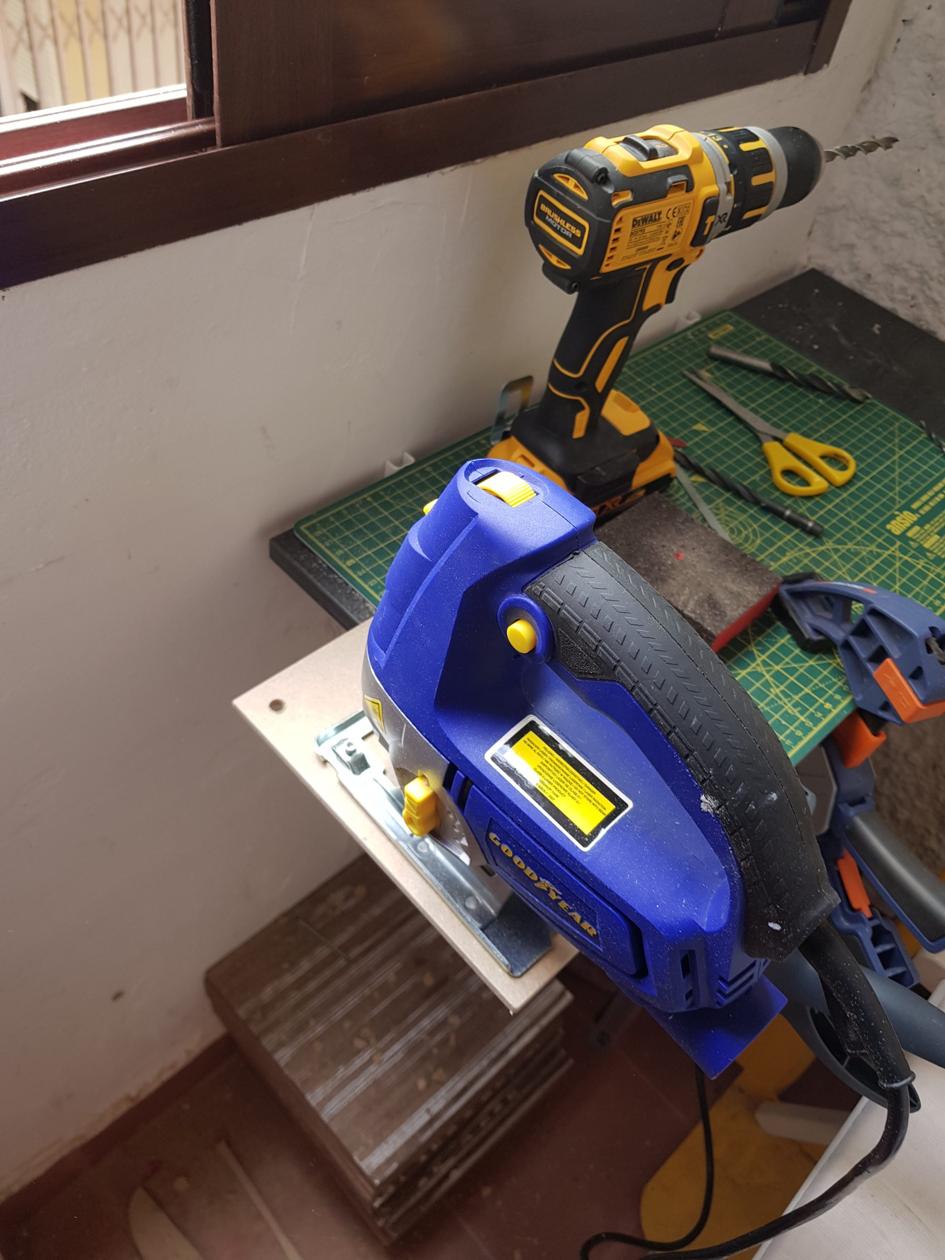
To easily cut out your H-pattern drill large holes then use a jigsaw to carefully carve out the pattern. A rotary tool here would be useful to smoothen out the edges. For this build I was up against the clock and did not attempt to make it look good!
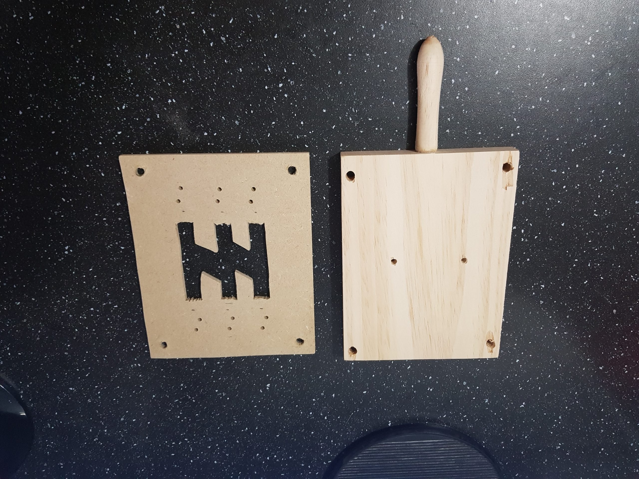
Once completed your MDF should now look something like this. Ready to be mounted to the rest of your gearstick.
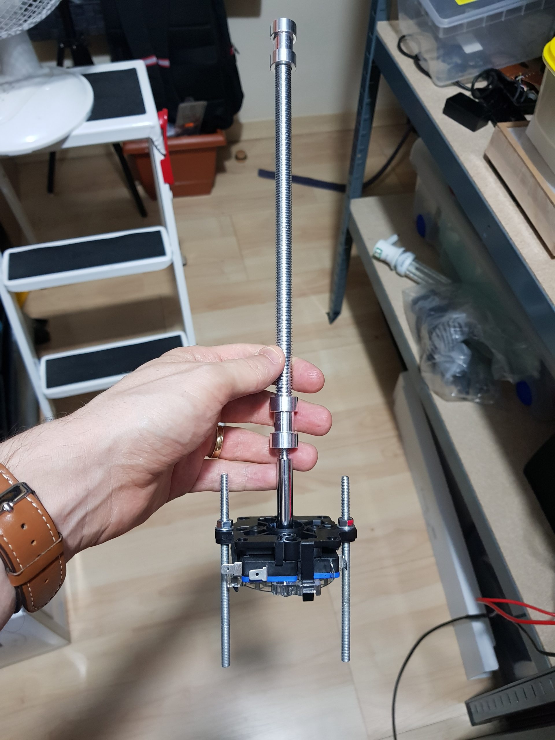
The gearstick
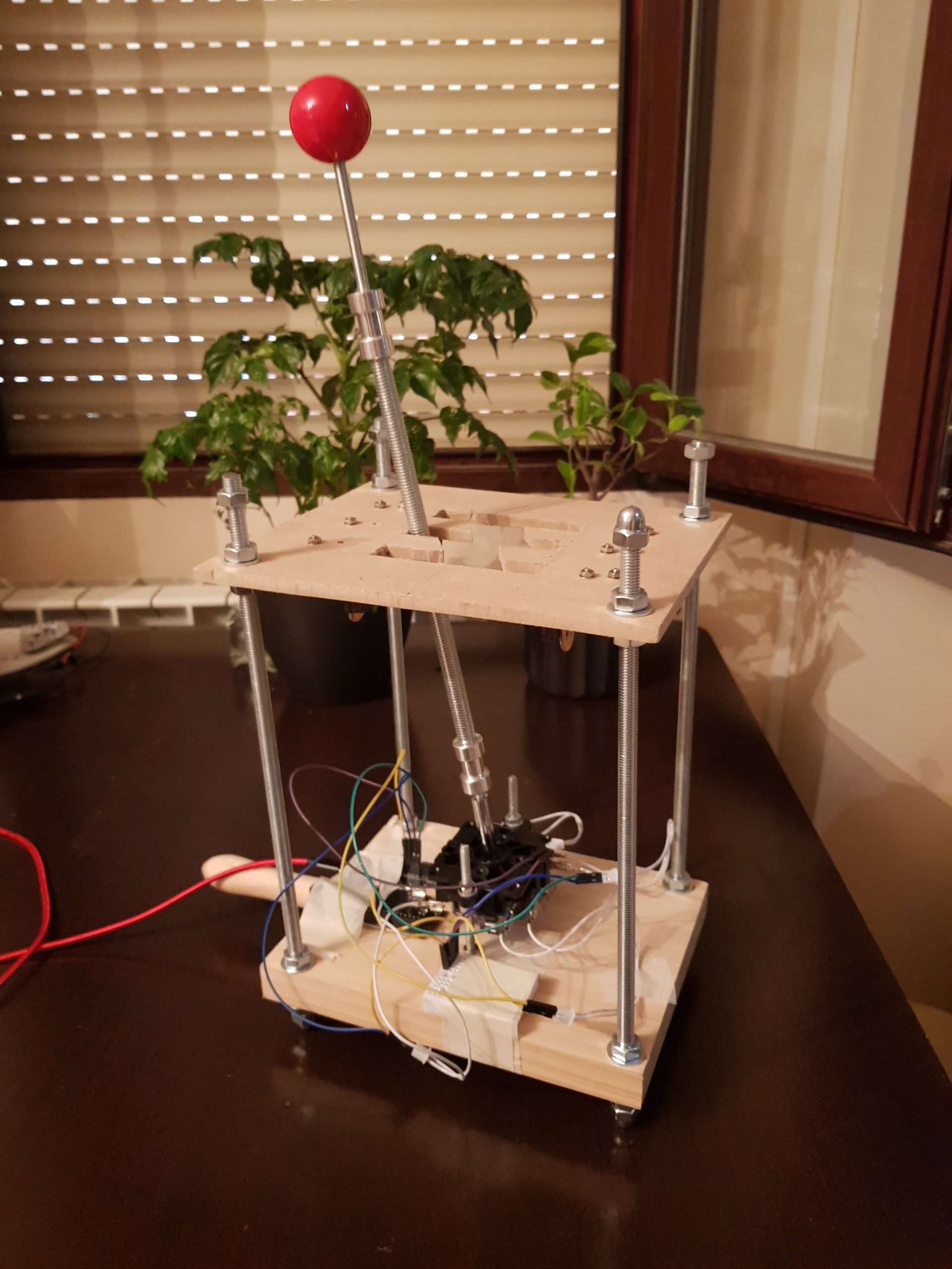
As it comes the joystick height is just a few cm. To look like a gear stick this needs to be much longer. I unscrewed the red handle and used a tripod size conversion module to be able to connect M8 sized threaded rod to the smaller rod that comes connected to the joystick. The length of this extension rod will depend on the desired height of your overall construction. We use the much thicker rod to give the gear stick the feeling of some weight, and it also works very well with the magnets. Finally, I used another tripod rod size conversion module with a few CM of smaller threaded rod to connect the red joystick head again.
Gears that stick
When driving an actual car, changing from neutral into first gear, leaves the gear stick placed in the first gear position. You may have questioned how our joystick will work as a gear stick, seeing as when left to its own devices it returns to the central position. That is a good question, and is the principal obstacle to overcome when building a DIY gear shifter.
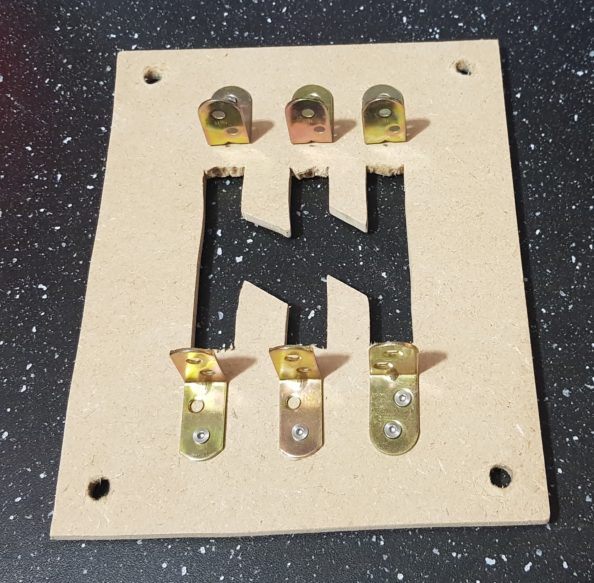
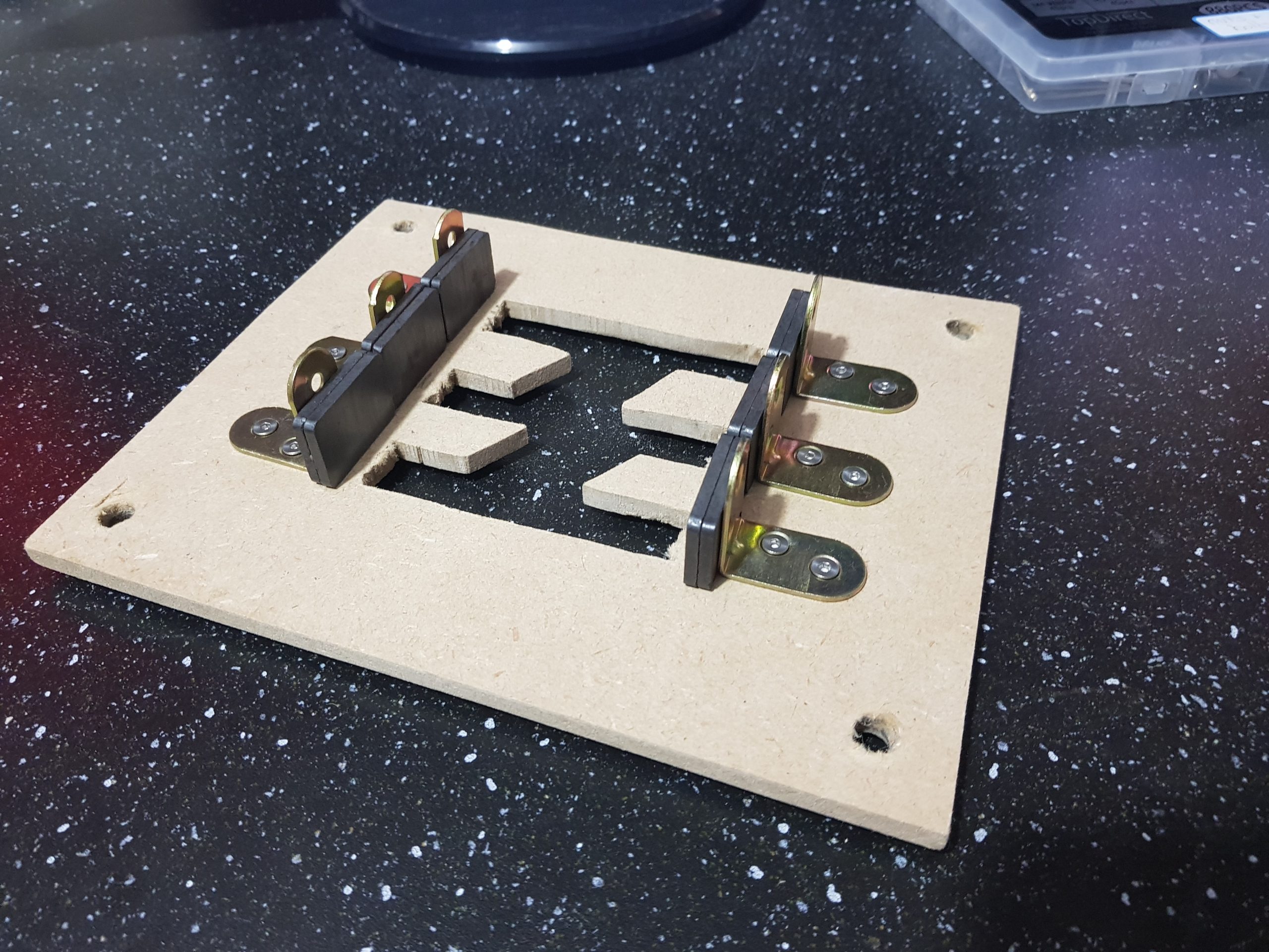
For my design, I chose to use magnets to hold the joystick in position. We mount L brackets at the end of each part of the H shifter pattern on the underside of the top board. We then place magnets, two for each gear in my case, at each gear. You could experiment with using more or less magnets. Personally I mounted the L brackets a little far from the gear stick, it still works correctly, but I could have placed them nearer and increased the grip the magnets would have on the stick.
Putting it all together
When you are satisfied that the height of your top board is correct and the gear stick is moving to each position and correctly being gripped by the magnets you should use nuts and washers underneath and above the top board to fix it in place. The great thing about constructions like this that use threaded rods is that adjusting the height is very easy.
I calculated the best height for my situation and here is how the final build looks. As you can see the stick is holding itself nicely in 3rd gear, thanks to the magnets underneath the top platform.
Wiring
I am using ‘jamma leads’ to connect the joystick module to my Leonardo board via some ‘du-pont’ breadboard wires.You could just as easily use any type of wire that could be connected properly. I noticed that some joystick modules available on AliExpress now have several smaller pin connectors rather than the jamma connectors.
Please do not judge my wiring in the photos! This was a prototype was I have not made any effort to organise the wiring.
Testing your gear shifter
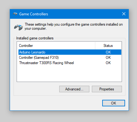
With everything plugged in Windows should recognise your USB H-shifter as a joystick. Use the Windows ‘Setup USB game controllers’ dialog to test your device. If all is well then moving from gear to gear should highlight a different button. As you can see Windows lists my gear stick as ‘Arduino Leonardo’.
Here is a short video demonstrating how the finished build works. I will shortly upload a video showing the gear stick in action.
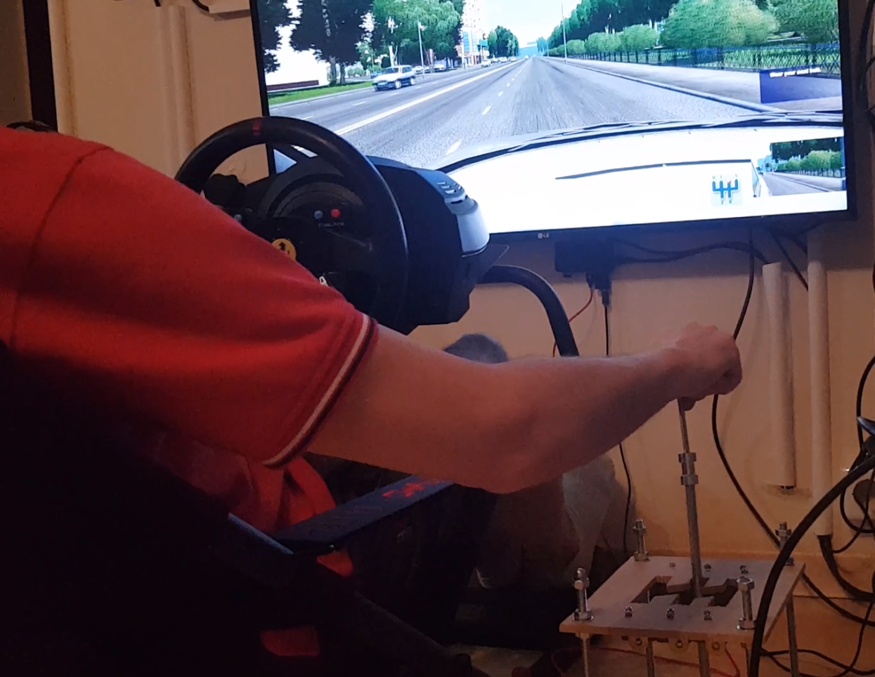
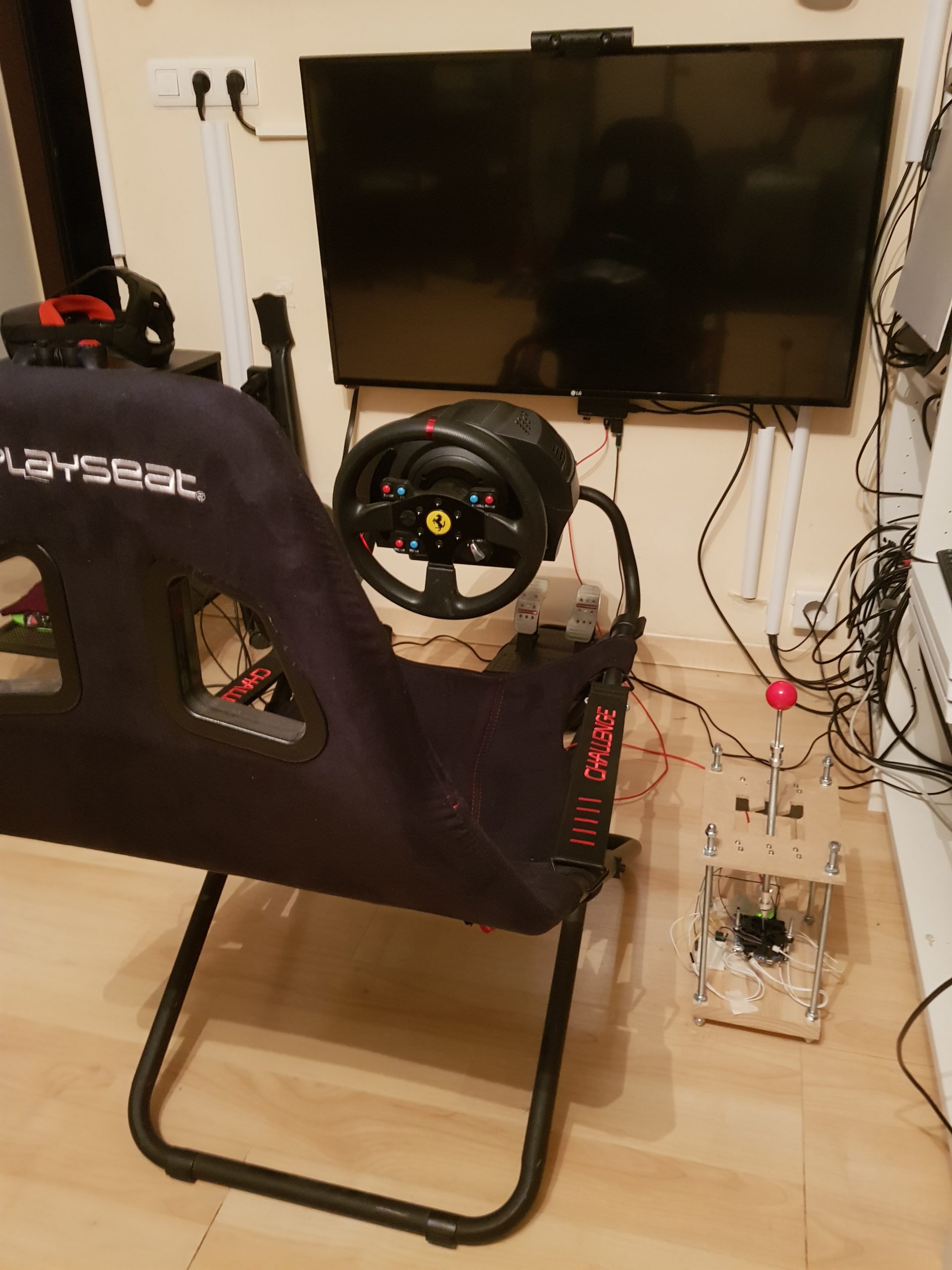
Here is how the final setup looks next to my T300RS wheel, pedals, and Playseat Challenge. I am currently working on a video demonstrating the gear stick in use.
Final Thoughts
Please do let me know if this tutorial has been useful. I deliberately tried to make this the simplest possible version. There are so many improvements that could be made. I intend to do another build and add the following features.
- A larger unit to give room for several buttons – in fact – as buttons are cheap and there are always actions to bind to buttons in games, I might add 8 or 10. These could be used in driving simulations to control lights, the engine, the horn, the radio etc.
- I also plan to add some DIP switches to the build, so that I can change how the device behaves without needing to reupload the software. It would be useful to have the option to set whether neutral ‘as a pressed button’ was enabled or not.
- I might also add a socket to plug in a clutch pedal. I could then pass on the data for the clutch pedal to the computer, while using the clutch pedal position to determine if a gear change should be successful or not. Perhaps playing a rough sound if the clutch wasn’t pressed correctly when the gear stick was moved, and stopping the gear change by throwing you into neutral.
- An LCD screen could be hooked up to show the current gear, and with a small program running on the host computer there is the potential to send back data such as speed/race position/revs etc where the game makes that information available.
If you decide to build this, good luck! As I said during the tutorial, the most important thing is getting the joystick mounted level, everything else can be tweaked easily.
Here is a video demonstrating the gear stick in use. Watch in full screen so that you can see the in-game gear graphic easily.
Aug 14 2020 – One month update
So a month later the gear stick is still working fine. The only issue is that at times it isn’t “clicking” properly into first gear. I figured out that this is because the rod connecting to the joystick isn’t perfectly straight, so the gear stick goes up at an angle slightly. The result of this is that occasionally pushing into first gear doesn’t quite work. Resolving this will simply be a case of connecting the rod to the joystick better. A slight rotation of the gear stick solves it and so I haven’t yet made that alteration.
[…] the input devices alone get you most of the way there. [Oli] decided he wanted a quick and easy USB gear shifter so he took a trip to the hardware store, picked up an arcade joystick, and tied it all together […]
[…] If you’d like to add a gear stick to your PC racing game experience, then Oli Norwell has just the project for you. […]
abaut this: I might also add a socket to plug in a clutch pedal. I could then pass on the data for the clutch pedal to the computer, while using the clutch pedal position to determine if a gear change should be successful or not. Perhaps playing a rough sound if the clutch wasn’t pressed correctly when the gear stick was moved, and stopping the gear change by throwing you into neutral.
think on change the magnets for electromagnets, if the change if the clutch wasn’t pressed correctly disable the magnets and the gear change will not remain in this place
This would definitely be the right away to go about it. Right now I don’t have enough electromagnets/solenoids. I wonder if some like this might work well: https://www.aliexpress.com/item/32815809960.html
Perhaps for version 2 I’ll investigate. I could put a reed switch under the Thrustmaster clutch pedal that I have, and a small magnet, then when the clutch was fully pressed that could feed across to my gear stick.
It’s a shame this isn’t on Github
https://github.com/ozzeruk/OTNGears
There you go – hope that helps
can you give us a wiring diagram?
Hey can you give some tips to wiring? I’m new in arduino and electronics.